Lenovo V4400u Hardware Maintenance Manual - Lenovo V4400u
Lenovo V4400u Manual
 |
View all Lenovo V4400u manuals
Add to My Manuals
Save this manual to your list of manuals |
Lenovo V4400u manual content summary:
- Lenovo V4400u | Hardware Maintenance Manual - Lenovo V4400u - Page 1
Hardware Maintenance Manual Lenovo V4400u - Lenovo V4400u | Hardware Maintenance Manual - Lenovo V4400u - Page 2
and the product it supports, be sure to read the general information under Appendix A "Notices" on page 85. Second Edition (August 2013) © Copyright Lenovo 2013. LIMITED AND RESTRICTED RIGHTS NOTICE: If data or software is delivered pursuant a General Services Administration "GSA" contract, use - Lenovo V4400u | Hardware Maintenance Manual - Lenovo V4400u - Page 3
Contents About this manual iii Chapter 1. Safety information . . . . . 1 General safety 1 Electrical safety 1 Safety inspection guide 3 Handling devices charging 23 Checking the battery pack 23 Chapter 3. Important service information 25 Recovering the computer settings 25 Using passwords 25 - Lenovo V4400u | Hardware Maintenance Manual - Lenovo V4400u - Page 4
ii Hardware Maintenance Manual - Lenovo V4400u | Hardware Maintenance Manual - Lenovo V4400u - Page 5
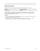
safety guidelines and important notices for servicing the computer. Important: • This manual is intended only for trained service technicians who are familiar with Lenovo products. Use this manual to troubleshoot problems effectively. • Before servicing a Lenovo product, ensure that you read - Lenovo V4400u | Hardware Maintenance Manual - Lenovo V4400u - Page 6
iv Hardware Maintenance Manual - Lenovo V4400u | Hardware Maintenance Manual - Lenovo V4400u - Page 7
chapter presents following safety information that you need to be familiar with before you service a Lenovo notebook computer. • "General safety" on page 1 • "Electrical safety" on page 1 • "Safety inspection guide" on page 3 • "Handling devices that are sensitive to electrostatic discharge" on page - Lenovo V4400u | Hardware Maintenance Manual - Lenovo V4400u - Page 8
precautions when you work with very high voltages; Instructions for these precautions are in the safety sections of touching can cause personal injury and machine damage. • Do not service the following parts with the power on when they are removed from medical aid. 2 Hardware Maintenance Manual - Lenovo V4400u | Hardware Maintenance Manual - Lenovo V4400u - Page 9
required safety items were installed to protect users and service technicians from injury. This guide addresses only those items. You should use good hazard could be and whether you can continue without first correcting the problem. Consider these conditions and the safety hazards they present: • - Lenovo V4400u | Hardware Maintenance Manual - Lenovo V4400u - Page 10
grounding system, such as those listed below, to provide protection that meets the specific service requirement. Note: The use of a grounding system to guard against ESD damage is German • Hebrew • Japanese • Korean • Spanish • Traditional Chinese DANGER DANGER 4 Hardware Maintenance Manual - Lenovo V4400u | Hardware Maintenance Manual - Lenovo V4400u - Page 11
DANGER DANGER DANGER DANGER DANGER Chapter 1. Safety information 5 - Lenovo V4400u | Hardware Maintenance Manual - Lenovo V4400u - Page 12
DANGER 6 Hardware Maintenance Manual - Lenovo V4400u | Hardware Maintenance Manual - Lenovo V4400u - Page 13
Chapter 1. Safety information 7 - Lenovo V4400u | Hardware Maintenance Manual - Lenovo V4400u - Page 14
PERIGO PERIGO PERIGO PERIGO PERIGO PERIGO 8 Hardware Maintenance Manual - Lenovo V4400u | Hardware Maintenance Manual - Lenovo V4400u - Page 15
PERIGO PERIGO DANGER DANGER DANGER Chapter 1. Safety information 9 - Lenovo V4400u | Hardware Maintenance Manual - Lenovo V4400u - Page 16
DANGER DANGER DANGER DANGER DANGER VORSICHT 10 Hardware Maintenance Manual - Lenovo V4400u | Hardware Maintenance Manual - Lenovo V4400u - Page 17
VORSICHT VORSICHT VORSICHT VORSICHT Chapter 1. Safety information 11 - Lenovo V4400u | Hardware Maintenance Manual - Lenovo V4400u - Page 18
VORSICHT VORSICHT VORSICHT 12 Hardware Maintenance Manual - Lenovo V4400u | Hardware Maintenance Manual - Lenovo V4400u - Page 19
Chapter 1. Safety information 13 - Lenovo V4400u | Hardware Maintenance Manual - Lenovo V4400u - Page 20
14 Hardware Maintenance Manual - Lenovo V4400u | Hardware Maintenance Manual - Lenovo V4400u - Page 21
Chapter 1. Safety information 15 - Lenovo V4400u | Hardware Maintenance Manual - Lenovo V4400u - Page 22
16 Hardware Maintenance Manual - Lenovo V4400u | Hardware Maintenance Manual - Lenovo V4400u - Page 23
Chapter 1. Safety information 17 - Lenovo V4400u | Hardware Maintenance Manual - Lenovo V4400u - Page 24
18 Hardware Maintenance Manual - Lenovo V4400u | Hardware Maintenance Manual - Lenovo V4400u - Page 25
Chapter 1. Safety information 19 - Lenovo V4400u | Hardware Maintenance Manual - Lenovo V4400u - Page 26
20 Hardware Maintenance Manual - Lenovo V4400u | Hardware Maintenance Manual - Lenovo V4400u - Page 27
checkout instructions, ensure that you read the following important notes. Important notes: • Only certified trained personnel should service the electrostatic discharge, or software errors. Consider replacing a FRU only when a problem recurs. If you suspect that a FRU is defective, clear the error - Lenovo V4400u | Hardware Maintenance Manual - Lenovo V4400u - Page 28
activities: • Missing parts might be a symptom of unauthorized service or modification. • If the spindle of a hard disk pack supplies power when you turn on the computer. If you suspect a power problem, refer to the following topics for a checkout: • "Checking the ac power Maintenance Manual - Lenovo V4400u | Hardware Maintenance Manual - Lenovo V4400u - Page 29
• If the voltage is acceptable, do the following: a. Replace the system board. b. If the problem persists, call the Customer Support Center. Note: Noise from the ac power adapter does not always indicate a defect. Checking operational charging To check whether the battery pack charges properly - Lenovo V4400u | Hardware Maintenance Manual - Lenovo V4400u - Page 30
5. Replace the system board if the new battery pack is not charged. 24 Hardware Maintenance Manual - Lenovo V4400u | Hardware Maintenance Manual - Lenovo V4400u - Page 31
can set the following types of passwords to protect unauthorized access to your computer. Attention: If you forget the password, there is no service procedure to reset the password. The system board must be replaced for a scheduled fee. • Power-on password: A power-on password protects the computer - Lenovo V4400u | Hardware Maintenance Manual - Lenovo V4400u - Page 32
, the hard disk drive, the parallel connector, or the diskette drive within that time. • The timer conditions are satisfied in suspend mode. 26 Hardware Maintenance Manual - Lenovo V4400u | Hardware Maintenance Manual - Lenovo V4400u - Page 33
When the power is turned on, the computer returns from hibernation mode and resumes operation. The hibernation file in the boot record on the hard disk drive is read, and the system status is restored from the hard disk drive. Chapter 3. Important service information 27 - Lenovo V4400u | Hardware Maintenance Manual - Lenovo V4400u - Page 34
28 Hardware Maintenance Manual - Lenovo V4400u | Hardware Maintenance Manual - Lenovo V4400u - Page 35
Chapter 4. Status indicators This topic presents the system status indicators that show the status of the computer. 32 1 Table 1. Status indicators Indicator 1 Active Protection System™ status indicator 2 Device access status indicator 3 Battery status indicator Meaning Your computer might come - Lenovo V4400u | Hardware Maintenance Manual - Lenovo V4400u - Page 36
30 Hardware Maintenance Manual - Lenovo V4400u | Hardware Maintenance Manual - Lenovo V4400u - Page 37
Chapter 5. Fn key combinations The following table describes the functions of Fn key combinations. Table 2. Function key combinations Key combination Fn+Esc Fn+Space Fn+F1 Fn+F2 Fn+F3 Fn+F5 Fn+F6 Fn+F8 Fn+F9 Fn+F10 Fn+F11 Fn+F12 Fn+PgUp Fn+PrtSc Fn+Home Fn+End Fn+PgDn Fn + up/down arrow Fn + left/ - Lenovo V4400u | Hardware Maintenance Manual - Lenovo V4400u - Page 38
32 Hardware Maintenance Manual - Lenovo V4400u | Hardware Maintenance Manual - Lenovo V4400u - Page 39
Chapter 6. Locations This chapter provides information about component locations. Locating computer controls, connectors, and indicators This topic introduces the locations of the computer controls, connectors, and indicators. Front view 2 12 12 3 11 10 9 8 7 65 4 Figure 1. Front view 1 Camera - Lenovo V4400u | Hardware Maintenance Manual - Lenovo V4400u - Page 40
service CRU. A Letter "N" in the CRU ID column means that the part is not a CRU. • CRU statement for customers: You can resolve some problems Manual. An electronic version of this manual can be found at http://www.lenovo.com/UserManuals. Follow the on-screen instructions to find the manual for - Lenovo V4400u | Hardware Maintenance Manual - Lenovo V4400u - Page 41
- Optional-service CRUs: These CRUs are isolated parts within the computer that are concealed by an access panel that is typically secured by more than two screws. - Lenovo V4400u | Hardware Maintenance Manual - Lenovo V4400u - Page 42
FRUs and CRUs Lenovo M4400s models use a 356-cm (14.0-inch), high-definition (HD), light-emitting diode (LED), liquid crystal display (LCD). 8 1 2 7 3 6 4 5 36 Hardware Maintenance Manual - Lenovo V4400u | Hardware Maintenance Manual - Lenovo V4400u - Page 43
Table 4. LCD FRUs No. 1 2 3 4 5 6 7 8 FRU description LCD Bezel Camera and microphones board Hinges Antennas LCD cover LCD cable LCD panel LCD bezel CRU ID N N N N N N N N Looking up FRU information For detailed FRU information, including part numbers, descriptions, and substitution part numbers, - Lenovo V4400u | Hardware Maintenance Manual - Lenovo V4400u - Page 44
38 Hardware Maintenance Manual - Lenovo V4400u | Hardware Maintenance Manual - Lenovo V4400u - Page 45
customers: You can resolve some problems with your product with a Manual. An electronic version of this manual can be found at http://www.lenovo.com/UserManuals. Follow the on-screen instructions to find the manual from the Lenovo Support Web site http://www.lenovo.com/support. • Before installing - Lenovo V4400u | Hardware Maintenance Manual - Lenovo V4400u - Page 46
If you are instructed to replace either the processor board or the system board, but the replacement does not solve the problem, reinstall the original vibration. • They are harder to tighten. Do the following when you are servicing the computer: • Keep the screw kit in your tool bag. • It Manual - Lenovo V4400u | Hardware Maintenance Manual - Lenovo V4400u - Page 47
This chapter provides instructions on how to remove or replace a FRU. CRU statement for customers: You can resolve some problems with your product with a replacement part you can install yourself, called a "Customer Replaceable Unit" or "CRU." Some CRUs are designated as self-service CRUs and others - Lenovo V4400u | Hardware Maintenance Manual - Lenovo V4400u - Page 48
1010 Lenovo OneLink connector cover Removal steps of the Lenovo OneLink connector cover Remove the connector cover as shown in the following illustration. Note: Ensure that you reattach the connector cover to the Lenovo OneLink connector after finishing the servicing. 42 Hardware Maintenance Manual - Lenovo V4400u | Hardware Maintenance Manual - Lenovo V4400u - Page 49
1020 Base cover Removal steps of the base cover Remove the screws 1 , and then remove the base cover 2 . 1 1 1 1 2 1 1 1 1 Step 1 Screw (quantity) M2 × 4.5 mm, flat-head, nylon-coated (8) Color Black Torque 0.181 Nm (1.85 kgf-cm) Applying labels to the base cover The new base cover is - Lenovo V4400u | Hardware Maintenance Manual - Lenovo V4400u - Page 50
Battery pack DANGER Use only the battery specified in the parts list for your computer. Any other battery could ignite or explode. 44 Hardware Maintenance Manual - Lenovo V4400u | Hardware Maintenance Manual - Lenovo V4400u - Page 51
Disconnect the connector 1 , and then remove the screw 2 . 2 2 1 2 Step 2 Screw (quantity) M2 × 4 mm, flat-head, nylon-coated (3) Remove the battery pack 3 . 3 Color Black Torque 0.181 Nm (1.85 kgf-cm) When installing: Ensure that the connector is firmly attached. 1040 Backup battery For - Lenovo V4400u | Hardware Maintenance Manual - Lenovo V4400u - Page 52
downward until it snaps into place. Ensure that the memory module is firmly installed in the slot and does not move easily. 46 Hardware Maintenance Manual - Lenovo V4400u | Hardware Maintenance Manual - Lenovo V4400u - Page 53
1060 PCI Express Mini Card for wireless LAN For access, remove this FRU: "1020 Base cover" on page 43 Removal steps of the PCI Express Mini Card for wireless LAN Unplug the connectors by using the antenna RF connector or pick up the connectors with your fingers and gently unplug them 1 . Then remove - Lenovo V4400u | Hardware Maintenance Manual - Lenovo V4400u - Page 54
-coated (1) Remove the M.2 solid-state drive. 2 1080 Hard disk drive assembly For access, remove this FRU: "1020 Base cover" on page 43 48 Hardware Maintenance Manual Color Black Torque 0.181 Nm (1.85 kgf-cm) - Lenovo V4400u | Hardware Maintenance Manual - Lenovo V4400u - Page 55
possible. • Never remove the drive while the computer is operating or in suspend mode. • The drive startup sequence in the computer you are servicing might have been changed. Be extremely careful during write operations such as copying, saving, or formatting. If you select an incorrect drive, data - Lenovo V4400u | Hardware Maintenance Manual - Lenovo V4400u - Page 56
disk drive bracket Remove the screws 1 . 1 1 Step 1 Screw (quantity) M3 × 3 mm, flat-head, nylon-coated (4) 1 1 Color Silver Torque 0.392 Nm (4.0 kgf-cm) 50 Hardware Maintenance Manual - Lenovo V4400u | Hardware Maintenance Manual - Lenovo V4400u - Page 57
Remove the hard disk drive bracket 2 . 2 1090 Fingerprint board bracket and fingerprint board For access, remove this FRU: "1020 Base cover" on page 43 Removal steps of the fingerprint board bracket and fingerprint board Remove the screw 1 , and then remove the fingerprint board bracket 2 . 1 2 - Lenovo V4400u | Hardware Maintenance Manual - Lenovo V4400u - Page 58
fingerprint board 5 . 5 1100 Speaker assembly For access, remove these FRUs: • "1020 Base cover" on page 43 • "1030 Battery pack" on page 44 52 Hardware Maintenance Manual - Lenovo V4400u | Hardware Maintenance Manual - Lenovo V4400u - Page 59
Removal steps of the speaker assembly Detach the connector 1 and then remove the screws and 2 . 2 1 2 Step 2 Screw (quantity) M2.5 × 2.5 mm, flat-head, nylon-coated (2) Remove the speaker assembly 3 . 3 3 Color Black Torque 0.392 Nm (4.0 kgf-cm) 1110 Touch panel For access, remove these FRUs - Lenovo V4400u | Hardware Maintenance Manual - Lenovo V4400u - Page 60
Nm (1.85 kgf-cm) When installing: Ensure that the connector is attached firmly to the system board. Remove the touch panel bracket 4 . 1 4 54 Hardware Maintenance Manual - Lenovo V4400u | Hardware Maintenance Manual - Lenovo V4400u - Page 61
Remove the touch panel 5 . 1 5 1120 Hall sensor For access, remove these FRUs in order: • "1020 Base cover" on page 43 • "1030 Battery pack" on page 44 • "1100 Speaker assembly" on page 52 Removal steps of the fingerprint board bracket and fingerprint board Remove the screw 1 , and then remove the - Lenovo V4400u | Hardware Maintenance Manual - Lenovo V4400u - Page 62
board Detach the cable 1 , and then detach the connector 2 3 . 2 3 1 When installing: Ensure that the cable is firmly attached to the system board. 56 Hardware Maintenance Manual - Lenovo V4400u | Hardware Maintenance Manual - Lenovo V4400u - Page 63
Remove the screw 4 , and then remove the media card reader slot board 5 6 . 4 5 Step 4 Screw (quantity) M2 × 3 mm, flat-head, nylon-coated (1) Color Black Torque 0.181 Nm (1.85 kgf-cm) 6 0 7 1140 Thermal module assembly For access, remove this FRU: "1020 Base cover" on page 43 Removal steps - Lenovo V4400u | Hardware Maintenance Manual - Lenovo V4400u - Page 64
of 0.2 grams, on the part marked a and b as shown in the following illustrations. Either too much or too less application of grease can cause a thermal problem due to imperfect contact with a component. 58 Hardware Maintenance - Lenovo V4400u | Hardware Maintenance Manual - Lenovo V4400u - Page 65
For models with an integrated thermal module assembly a For models with a discrete thermal module assembly a b 1150 System board assembly For access, remove these FRUs in order: • "1020 Base cover" on page 43 • "1030 Battery pack" on page 44 • "1080 Hard disk drive assembly" on page 48 • "1070 M.2 - Lenovo V4400u | Hardware Maintenance Manual - Lenovo V4400u - Page 66
sensitive. Improper handling of a system board can cause damage to the following components, and might cause a system malfunction. When you service the system board, avoid any kind of rough handling. a Platform Controller Hub (PCH) b Microprocessor c Graphics chip (for discrete graphics models - Lenovo V4400u | Hardware Maintenance Manual - Lenovo V4400u - Page 67
Removal steps of the system board assembly Detach the connectors. 9 10 11 7 8 5 3 6 4 1 2 When installing: Ensure that all the connectors are firmly attached. Remove the screws. 13 13 12 12 12 12 Step 12 13 Screw (quantity) M2 × 4 mm, flat-head, nylon-coated (4) M2 × 4 mm, flat-head, - Lenovo V4400u | Hardware Maintenance Manual - Lenovo V4400u - Page 68
48 Removal steps of the I/O board Detach the connector 1 . 1 When installing: Ensure that the connector is attached firmly to the system board. 62 Hardware Maintenance Manual - Lenovo V4400u | Hardware Maintenance Manual - Lenovo V4400u - Page 69
Remove the screws 2 , and then remove the I/O board 3 . 2 2 3 Step 2 Screw (quantity) M2 × 4 mm, flat-head, nylon-coated (2) 1170 Thermal sensor For access, remove these FRUs in order: • "1020 Base cover" on page 43 • "1030 Battery pack" on page 44 • "1080 Hard disk drive assembly" on page 48 - Lenovo V4400u | Hardware Maintenance Manual - Lenovo V4400u - Page 70
Removal steps of the LCD unit Color Black Torque 0.392 Nm (4.0 kgf-cm) 2 1 When installing: Ensure that the connectors are firmly attached. 64 Hardware Maintenance Manual - Lenovo V4400u | Hardware Maintenance Manual - Lenovo V4400u - Page 71
33 3 Step 3 4 Screw (quantity) M2.5 × 5 mm, flat-head, nylon-coated (5) M2.0 × 4 mm, flat-head, nylon-coated (3) 5 6 5 5 6 33 4 4 4 Color Black Black Torque 0.392 Nm (4.0 kgf-cm) 0.181 Nm (1.85 kgf-cm) 7 When installing: Ensure that you route the cables firmly and tape up in the proper - Lenovo V4400u | Hardware Maintenance Manual - Lenovo V4400u - Page 72
that they are not subject to any tension. Tension could cause the cables to be damaged by the cable guides, or a wire to be broken. 2030 Touch control board and LCD panel For access, remove these FRUs in on page 69 Removal steps of the touch control board 1 2 3 66 Hardware Maintenance Manual 0 0 - Lenovo V4400u | Hardware Maintenance Manual - Lenovo V4400u - Page 73
0 5 4 6 7 8 Chapter 8. Removing or replacing a FRU 67 - Lenovo V4400u | Hardware Maintenance Manual - Lenovo V4400u - Page 74
Removal steps of the LCD panel 9 9 9 9 Step 9 Screw (quantity) M2 × 3 mm, flat-head, nylon-coated (4) 10 10 10 Color Black 10 11 10 Torque 0.181 Nm (1.85 kgf-cm) 10 10 10 10 10 10 10 14 13 10 10 12 68 Hardware Maintenance Manual - Lenovo V4400u | Hardware Maintenance Manual - Lenovo V4400u - Page 75
2020 LCD hinge kit For access, remove these FRUs in order: • "1020 Base cover" on page 43 • "1030 Battery pack" on page 44 • "2010 LCD Unit" on page 64 Removal steps of the LCD hinge cap Remove the screws 1 . 1 2 1 Step 1 Screw (quantity) M2 × 4 mm, flat-head, nylon-coated (2) Removal steps of - Lenovo V4400u | Hardware Maintenance Manual - Lenovo V4400u - Page 76
LCD Unit" on page 64 • "2020 LCD hinge kit" on page 69 • "2030 Touch control board and LCD panel" on page 66 70 Hardware Maintenance Manual - Lenovo V4400u | Hardware Maintenance Manual - Lenovo V4400u - Page 77
Removal steps of the camera-and-microphone-combo card Detach the connector 1 and then peel off the camera-and-microphone-combo card 2 . 2 1 When installing: Adhere the camera-and-microphone-combo card to the top center of the LCD cover and adjust the placement to ensure that the connector is firmly - Lenovo V4400u | Hardware Maintenance Manual - Lenovo V4400u - Page 78
and LCD panel" on page 66 • "2040 Camera-and-microphone-combo card" on page 70 • "2050 LCD cable assembly" on page 71 72 Hardware Maintenance Manual - Lenovo V4400u | Hardware Maintenance Manual - Lenovo V4400u - Page 79
Removal steps of the antenna kit and LCD rear cover 1 1 2 2 Cable routing: Route the antenna cables along the cable guides and secure the antenna boards with tapes. Attention: When you route the cables, ensure that they are not subject to any tension. Tension could damage - Lenovo V4400u | Hardware Maintenance Manual - Lenovo V4400u - Page 80
43 • "1030 Battery pack" on page 44 Removal steps of the LCD unit b 2 1 When installing: Ensure that the connectors are firmly attached. 74 Hardware Maintenance Manual - Lenovo V4400u | Hardware Maintenance Manual - Lenovo V4400u - Page 81
33 3 Step 3 4 Screw (quantity) M2.5 × 5 mm, flat-head, nylon-coated (5) M2.0 × 4 mm, flat-head, nylon-coated (3) 5 6 5 5 6 33 4 4 4 Color Black Black Torque 0.392 Nm (4.0 kgf-cm) 0.181 Nm (1.85 kgf-cm) 7 When installing: Ensure that you route the cables firmly and tape up in the proper - Lenovo V4400u | Hardware Maintenance Manual - Lenovo V4400u - Page 82
that they are not subject to any tension. Tension could cause the cables to be damaged by the cable guides, or a wire to be broken. 2020 LCD hinge kit For access, remove these FRUs in order: • , flat-head, nylon-coated (2) Color Black Torque 0.181 Nm (1.85 kgf-cm) 76 Hardware Maintenance Manual - Lenovo V4400u | Hardware Maintenance Manual - Lenovo V4400u - Page 83
Removal steps of the LCD hinge Remove the screws 1 . 1 1 1 11 1 Step 1 Screw (quantity) M2.5 × 3.5 mm, flat-head, nylon-coated (6) 2 Color Black Torque 0.392 Nm (4.0 kgf-cm) 2 2030 Touch control board and LCD panel For access, remove these FRUs in order: • "1020 Base cover" on page 43 • " - Lenovo V4400u | Hardware Maintenance Manual - Lenovo V4400u - Page 84
0 0 Removal steps of the touch control board 1 2 3 5 4 78 Hardware Maintenance Manual - Lenovo V4400u | Hardware Maintenance Manual - Lenovo V4400u - Page 85
0 6 7 8 Chapter 8. Removing or replacing a FRU 79 - Lenovo V4400u | Hardware Maintenance Manual - Lenovo V4400u - Page 86
Removal steps of the LCD panel 9 9 9 9 Step 9 Screw (quantity) M2 × 3 mm, flat-head, nylon-coated (4) 10 10 10 Color Black 10 11 10 Torque 0.181 Nm (1.85 kgf-cm) 10 10 10 10 10 10 10 14 13 10 10 12 80 Hardware Maintenance Manual - Lenovo V4400u | Hardware Maintenance Manual - Lenovo V4400u - Page 87
2040 Camera-and-microphone-combo card For access, remove these FRUs in order: • "1020 Base cover" on page 43 • "1030 Battery pack" on page 44 • "2010 LCD Unit" on page 74 • "2020 LCD hinge kit" on page 76 • "2030 Touch control board and LCD panel" on page 77 Removal steps of the camera-and- - Lenovo V4400u | Hardware Maintenance Manual - Lenovo V4400u - Page 88
Removal steps of the antenna kit and LCD rear cover 1 1 2 2 Cable routing: Route the antenna cables along the cable guides and secure the antenna boards with tapes. Attention: When you route the cables, ensure that they are not subject to any tension. Tension could damage - Lenovo V4400u | Hardware Maintenance Manual - Lenovo V4400u - Page 89
Antenna locations a Wireless LAN auxiliary antenna (black) b Wireless LAN main antenna (gray) a b Chapter 8. Removing or replacing a FRU 83 - Lenovo V4400u | Hardware Maintenance Manual - Lenovo V4400u - Page 90
84 Hardware Maintenance Manual - Lenovo V4400u | Hardware Maintenance Manual - Lenovo V4400u - Page 91
evaluate and verify the operation of any other product, program, or service. Lenovo may have patents or pending patent applications covering subject matter document are not intended for use in implantation or other life support applications where malfunction may result in injury or death to persons - Lenovo V4400u | Hardware Maintenance Manual - Lenovo V4400u - Page 92
in the United States, other countries or both: Lenovo OneKey Microsoft and Windows are trademarks of the Microsoft group of companies. Other company, product, or service names may be trademarks or service marks of others. 86 Hardware Maintenance Manual - Lenovo V4400u | Hardware Maintenance Manual - Lenovo V4400u - Page 93
- Lenovo V4400u | Hardware Maintenance Manual - Lenovo V4400u - Page 94
-
 1
1 -
 2
2 -
 3
3 -
 4
4 -
 5
5 -
 6
6 -
 7
7 -
8
-
9
-
10
-
11
-
12
-
13
-
14
-
15
-
16
-
17
-
18
-
19
-
20
-
21
-
22
-
23
-
24
-
25
-
26
-
27
-
28
-
29
-
30
-
31
-
32
-
33
-
34
-
35
-
36
-
37
-
38
-
39
-
40
-
41
-
42
-
43
-
44
-
45
-
46
-
47
-
48
-
49
-
50
-
51
-
52
-
53
-
54
-
55
-
56
-
57
-
58
-
59
-
60
-
61
-
62
-
63
-
64
-
65
-
66
-
67
-
68
-
69
-
70
-
71
-
72
-
73
-
74
-
75
-
76
-
77
-
78
-
79
-
80
-
81
-
82
-
83
-
84
-
85
-
86
-
87
-
88
-
89
-
90
-
91
-
92
-
93
-
94
 |
 |
Hardware Maintenance Manual
Lenovo V4400u