Lenovo V4400u Hardware Maintenance Manual - Lenovo V4400u - Page 52
Memory modules, memory module
 |
View all Lenovo V4400u manuals
Add to My Manuals
Save this manual to your list of manuals |
Page 52 highlights
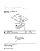
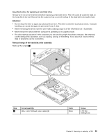
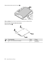
Disconnect the connector 1 and then remove the backup battery 2 . 2 1 1050 Memory modules For access, remove this FRU: "1020 Base cover" on page 43 Removal steps of the memory modules Release the two latches on both edges of the socket at the same time 1 , and then carefully remove the memory module 2 . 2 1 1 When installing: Insert the notched end of the memory module into the socket. Press the memory module firmly, and pivot it downward until it snaps into place. Ensure that the memory module is firmly installed in the slot and does not move easily. 46 Hardware Maintenance Manual
-
 1
1 -
2
-
3
-
4
-
5
-
6
-
7
-
8
-
9
-
10
-
11
-
12
-
13
-
14
-
15
-
16
-
17
-
18
-
19
-
20
-
21
-
22
-
23
-
24
-
25
-
26
-
27
-
28
-
29
-
30
-
31
-
32
-
33
-
34
-
35
-
36
-
37
-
38
-
39
-
40
-
41
-
42
-
43
-
44
-
45
-
46
-
 47
47 -
 48
48 -
 49
49 -
 50
50 -
 51
51 -
 52
52 -
 53
53 -
 54
54 -
 55
55 -
 56
56 -
 57
57 -
58
-
59
-
60
-
61
-
62
-
63
-
64
-
65
-
66
-
67
-
68
-
69
-
70
-
71
-
72
-
73
-
74
-
75
-
76
-
77
-
78
-
79
-
80
-
81
-
82
-
83
-
84
-
85
-
86
-
87
-
88
-
89
-
90
-
91
-
92
-
93
-
94
 |
 |

Disconnect the connector
1
and then remove the backup battery
2
.
1
2
1050 Memory modules
For access, remove this FRU:
“1020 Base cover” on page 43
Removal steps of the memory modules
Release the two latches on both edges of the socket at the same time
1
, and then carefully remove the
memory module
2
.
2
1
1
When installing:
Insert the notched end of the memory module into the socket. Press the memory module
firmly, and pivot it downward until it snaps into place. Ensure that the memory module is firmly installed
in the slot and does not move easily.
46
Hardware Maintenance Manual