Lenovo X200s Hardware Maintenance Manual
Lenovo X200s - ThinkPad 7466 - Core 2 Duo 2.13 GHz Manual
 |
UPC - 884942322655
View all Lenovo X200s manuals
Add to My Manuals
Save this manual to your list of manuals |
Lenovo X200s manual content summary:
- Lenovo X200s | Hardware Maintenance Manual - Page 1
ThinkPad® X200 and X200s Hardware Maintenance Manual - Lenovo X200s | Hardware Maintenance Manual - Page 2
- Lenovo X200s | Hardware Maintenance Manual - Page 3
ThinkPad® X200 and X200s Hardware Maintenance Manual - Lenovo X200s | Hardware Maintenance Manual - Page 4
using this information and the product it supports, be sure to read the general information under "Notices" on page 197. Fourth Edition (December 2008) © Copyright Lenovo 2008. All rights reserved. LENOVO products, data, computer software, and services have been developed exclusively at private - Lenovo X200s | Hardware Maintenance Manual - Page 5
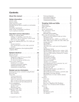
X200 and X200s 47 Specifications 48 Status indicators 51 FRU tests 53 Fn key combinations 55 FRU replacement notices 58 Screw notices 58 Retaining serial numbers 59 Removing and replacing a FRU 62 Before servicing ThinkPad X200 and X200s . . . 63 1010 Battery pack 64 1020 Hard disk drive - Lenovo X200s | Hardware Maintenance Manual - Page 6
Power cords 186 Recovery discs 187 Common service tools 195 Notices 197 Trademarks 198 iv ThinkPad X200 and X200s Hardware Maintenance Manual - Lenovo X200s | Hardware Maintenance Manual - Page 7
This manual contains service and reference information for the following ThinkPad® products. ThinkPad X200 MT 7454, 7455, 7457, 7458, 7459, 2023, and 2024 ThinkPad X200s MT 7462, 7465, 7466, 7469, 7470, 2046, and 2047 Use this manual along with the advanced diagnostic tests to troubleshoot problems - Lenovo X200s | Hardware Maintenance Manual - Page 8
vi ThinkPad X200 and X200s Hardware Maintenance Manual - Lenovo X200s | Hardware Maintenance Manual - Page 9
safety information that you need to be familiar with before you service a ThinkPad computer. v "General safety" on page 2 v "Electrical safety" on page 3 v "Safety inspection guide" on page 5 v "Handling devices that are sensitive to electrostatic discharge" on page 6 v "Grounding requirements" on - Lenovo X200s | Hardware Maintenance Manual - Page 10
or working in any other conditions that might be hazardous to your eyes. v After service, reinstall all safety shields, guards, labels, and ground wires. Replace any safety device that is fan louvers or cover them with labels or stickers. 2 ThinkPad X200 and X200s Hardware Maintenance Manual - Lenovo X200s | Hardware Maintenance Manual - Page 11
mat to protect yourself from electrical shock. v Find the room emergency power-off (EPO) switch, disconnecting switch, or electrical outlet. If an frames. Observe the special safety precautions when you work with very high voltages; Instructions for these precautions are in the safety sections of - Lenovo X200s | Hardware Maintenance Manual - Page 12
v Do not service the following parts with the power on when they are removed from their normal operating places in a machine: - Power supply units - Pumps not become a victim yourself. - Switch off power. - Send another person to get medical aid. 4 ThinkPad X200 and X200s Hardware Maintenance Manual - Lenovo X200s | Hardware Maintenance Manual - Page 13
installed to protect users and service personnel from injury. This guide addresses only those power cord should be the type specified in the parts list. c. Insulation must not be frayed or worn. 4. Check for cracked or bulging batteries. 5. Remove the cover. 6. Check for any obvious non-ThinkPad - Lenovo X200s | Hardware Maintenance Manual - Page 14
Use the black side of a grounded work mat to provide a static-free work surface. The mat is especially useful when handling ESD-sensitive devices. v Select a grounding system, such as those listed below, to provide protection that meets the specific service requirement. Note: The use of a grounding - Lenovo X200s | Hardware Maintenance Manual - Page 15
notices in this section are provided in English, French, German, Hebrew, Italian, Japanese, and Spanish. Safety notice 1 Before the computer is powered on after FRU replacement, make sure all screws, springs, and other small parts are in place and are not left loose inside the computer. Verify this - Lenovo X200s | Hardware Maintenance Manual - Page 16
la pile de sauvegarde ou celle de l'horloge temps réel, veillez à n'utiliser que les modèles cités dans la liste de pièces détachées adéquate. Une batterie ou une pile inappropriée apropiada puede provocar la ignición o explosión de la misma. 8 ThinkPad X200 and X200s Hardware Maintenance Manual - Lenovo X200s | Hardware Maintenance Manual - Page 17
pack as required by local ordinances or regulations. Use only the battery in the appropriate parts listing when replacing the battery pack. Use of an incorrect battery can result in ignition or explosion of the battery. La batterie contient du nickel. Ne la démontez pas, ne l'exposez ni au feu - Lenovo X200s | Hardware Maintenance Manual - Page 18
cell contents to water. Dispose of the battery as required by local ordinances or regulations. Use only the battery in the appropriate parts listing. Use of an incorrect battery can result in ignition or explosion of the battery normativa local. 10 ThinkPad X200 and X200s Hardware Maintenance Manual - Lenovo X200s | Hardware Maintenance Manual - Page 19
Safety notice 5 If the LCD breaks and the fluid from inside the LCD gets into your eyes or on your hands, immediately wash the affected areas with water for at least 15 minutes. Seek medical care if any symptoms from the fluid are present after washing. Si le panneau d'affichage à cristaux liquides - Lenovo X200s | Hardware Maintenance Manual - Page 20
brennbare Materialien zu entzünden oder Verletzungen bei Personen hervorzurufen. Sebbene le batterie di alimentazione siano a basso voltaggio, una batteria in corto circuito para quemar material combustible o provocar quemaduras en el personal. 12 ThinkPad X200 and X200s Hardware Maintenance Manual - Lenovo X200s | Hardware Maintenance Manual - Page 21
Safety notice 8 DANGER Before removing any FRU, power off the computer, unplug all power cords from electrical outlets, remove the battery pack, and then disconnect any interconnecting cables. Avant de retirer une unité remplaçable en clientèle, mettez le système hors tension, débranchez tous - Lenovo X200s | Hardware Maintenance Manual - Page 22
la exposición a radiaciones peligrosas. Opening the CD-ROM drive, the DVD-ROM drive, or any other optical storage device could result in exposure to hazardous laser radiation. There are no serviceable parts inside those drives. Do not open. 14 ThinkPad X200 and X200s Hardware Maintenance Manual - Lenovo X200s | Hardware Maintenance Manual - Page 23
A CD-ROM drive, a DVD-ROM drive, or any other storage device installed may contain an embedded Class 3A or Class 3B laser diode. Note the following: DANGER Emits visible and invisible laser radiation when open. Do - Lenovo X200s | Hardware Maintenance Manual - Page 24
16 ThinkPad X200 and X200s Hardware Maintenance Manual - Lenovo X200s | Hardware Maintenance Manual - Page 25
21 Important: BIOS and device driver fixes are customer-installable. The BIOS and device drivers are posted on the customer support site http://www.lenovo.com/support System Disassembly/Reassembly videos that show the FRU removals or replacements for the Lenovo® authorized service technicians are - Lenovo X200s | Hardware Maintenance Manual - Page 26
system board. If you are instructed to replace either the processor board or the system board, and replacing one of them does not correct the problem, reinstall that board, and then replace the other one. v If an adapter or a device servicing. 18 ThinkPad X200 and X200s Hardware Maintenance Manual - Lenovo X200s | Hardware Maintenance Manual - Page 27
- serial number level. An example of key commodities are hard disk drives, system boards, microprocessors, Liquid Crystal Displays (LCDs), and memory. /pc/ entitle/pg2/Service.wss/display/Home Customers can also access PEW via http://www-307.ibm.com/pc/support/site.wss/product.do?template=/warranty/ - Lenovo X200s | Hardware Maintenance Manual - Page 28
model and FRU will be displayed. Using the HMM For Key Commodities (Examples - hard disk drive, system board, microprocessor, LCD, and memory) Use the HMM as a back-up to PEW and eSupport to view the complete list of FRUs at the MT Model level. 20 ThinkPad X200 and X200s Hardware Maintenance Manual - Lenovo X200s | Hardware Maintenance Manual - Page 29
to support Lenovo's Lenovo produces containing RoHS compliant FRUs. RoHS compliant FRUs have unique FRU part numbers. Before or after the RoHS implementation date, failed RoHS compliant parts must always be replaced using RoHS compliant FRUs, so only the FRUs identified as compliant in the system - Lenovo X200s | Hardware Maintenance Manual - Page 30
22 ThinkPad X200 and X200s Hardware Maintenance Manual - Lenovo X200s | Hardware Maintenance Manual - Page 31
page 24 v "Checkout guide" on page 25 - "Diagnostics using PC-Doctor for DOS" on page 26 - "PC-Doctor for Windows" on page 28 - "PC-Doctor for Rescue and Recovery" on page 28 v "Power system checkout" on page 29 The descriptions in this chapter apply to any ThinkPad model that supports the PC-Doctor - Lenovo X200s | Hardware Maintenance Manual - Page 32
that the system was subjected to stress beyond normal use. Before checking problems with the computer service or modification. v If the spindle of a hard disk drive becomes noisy, it may have been subjected to excessive force, or dropped. 24 ThinkPad X200 and X200s Hardware Maintenance Manual - Lenovo X200s | Hardware Maintenance Manual - Page 33
procedures as a guide in identifying and correcting problems with the ThinkPad computer. Note: The diagnostic tests are intended to test only ThinkPad products. The use of non-ThinkPad products, prototype cards, or modified options can lead to false indications of errors and invalid system responses - Lenovo X200s | Hardware Maintenance Manual - Page 34
the computer configuration, some devices are disabled, such as the serial port. If you test one of these devices, you will need to enable it by using Configuration utility for DOS. The utility is available on the following Web site: http://www.lenovo.com/support Testing the computer To run - Lenovo X200s | Hardware Maintenance Manual - Page 35
v CPU/Coprocessor v Systemboard v Video Adapter v Serial Ports v Parallel Ports v Fixed Disks v Diskette Drives v Other Devices v ThinkPad Devices v Communication v Wireless LAN v PM Memory v Keyboard v Video v Internal Speaker v Mouse v Diskette v System Load v Optical Drive Test v Intel 5XXX WLAN - Lenovo X200s | Hardware Maintenance Manual - Page 36
Tests v Surface Scan Hard Disk v Benchmark System v DOS Shell v Tech Support Form v Battery Rundown v View Test Log v Print Log v Save Log v Full Erase Hard Drive v Quick Erase Hard Drive PC-Doctor for Windows This product is designed to help you troubleshoot and resolve problems related to your - Lenovo X200s | Hardware Maintenance Manual - Page 37
of pin no.2 of the ac adapter may different from the one you are servicing. 3. If the voltage is not correct, replace the ac adapter. 4. If the voltage is acceptable, do the following: v Replace the system board. v If the problem persists, go to "ThinkPad X200 and X200s" on page 47. Note: Noise from - Lenovo X200s | Hardware Maintenance Manual - Page 38
voltage is more than +11.0 V dc, measure the resistance between battery terminals 5 and 7. The resistance must be 4 to 30 K . If the resistance is not correct, replace the battery pack. If the resistance is correct, replace the system board. 30 ThinkPad X200 and X200s Hardware Maintenance Manual - Lenovo X200s | Hardware Maintenance Manual - Page 39
Checking the backup battery Do the following: 1. Power off the computer, and unplug the ac adapter from it. 2. Turn the computer upside down. 3. Remove the battery pack (see "1010 Battery pack" on page 64). 4. Remove the backup battery (see "1060 Backup battery" on page 77). 5. Measure the voltage - Lenovo X200s | Hardware Maintenance Manual - Page 40
32 ThinkPad X200 and X200s Hardware Maintenance Manual - Lenovo X200s | Hardware Maintenance Manual - Page 41
the latest maintenance diskette and the system program service diskette become available, they will be posted on http://www.lenovo.com/spm Restoring the factory contents by using Product Recovery discs When the hard disk drive (HDD) or solid state drive (SSD) is replaced because of a failure, no - Lenovo X200s | Hardware Maintenance Manual - Page 42
is complete, the Welcome to Microsoft Windows screen is displayed. Follow the instructions on the screen to complete the Windows setup. Passwords As many as three passwords may be needed for any ThinkPad computer: the power-on password (POP), the hard-disk password (HDP), and the supervisor - Lenovo X200s | Hardware Maintenance Manual - Page 43
and cannot be made available to the servicer, neither Lenovo nor Lenovo authorized servicers provide any services to reset the user HDPs or to recover data from the hard disk drive. The hard disk drive can be replaced for a scheduled fee. To remove a user HDP that has been forgotten, when the - Lenovo X200s | Hardware Maintenance Manual - Page 44
the Enter Current Password field. then leave the Enter New Password field blank, and press Enter twice. 8. Press F10. 9. Select Yes in the Setup Configuration window. Both user HDP and master HDP will have been removed. 36 ThinkPad X200 and X200s Hardware Maintenance Manual - Lenovo X200s | Hardware Maintenance Manual - Page 45
drive within that time. v If the battery indicator blinks orange, indicating that the battery power is low. (Alternatively, if Hibernate when battery becomes low has been selected in the "Power Management Properties" window, the computer goes into hibernation mode.) Note for the APM operating system - Lenovo X200s | Hardware Maintenance Manual - Page 46
battery charge becomes critically low. When the power is turned on, the computer returns from hibernation mode and resumes operation. The hibernation file in the boot record on the hard disk drive is read, and system status is restored from the hard disk drive. 38 ThinkPad X200 and X200s Hardware - Lenovo X200s | Hardware Maintenance Manual - Page 47
descriptions of symptoms. If the symptom is not described there, go to "Intermittent problems" on page 46. Note: For a device not supported by diagnostic codes in the ThinkPad computers, see the manual for that device. Numeric error codes Table 1. Numeric error codes Symptom or error FRU or - Lenovo X200s | Hardware Maintenance Manual - Page 48
0230 Shadow RAM error-Shadow RAM fails at offset nnnn. System board. 0231 System RAM error-System RAM fails at offset nnnn. 1. DIMM. 2. System board. 0232 1. DIMM. Extended RAM error- Extended RAM fails 2. System board. at offset nnnn. 40 ThinkPad X200 and X200s Hardware Maintenance Manual - Lenovo X200s | Hardware Maintenance Manual - Page 49
error codes (continued) Symptom or error FRU or action, in sequence 0250 System battery error-System battery is dead. 1. Charge the backup battery for more than 8 hours by connecting the ac adapter. 2. Replace the backup battery and run BIOS Setup Utility to reset the time and date. 0251 - Lenovo X200s | Hardware Maintenance Manual - Page 50
Reseat the hard disk drive. Read error on HDD0 (Main hard disk drive) 2. Main hard disk drive. 3. System board. 2112 Read error on HDD1 (Ultrabay hard disk drive) 1. Reseat the hard disk drive. 2. Ultrabay hard disk drive. 3. System board. 42 ThinkPad X200 and X200s Hardware Maintenance Manual - Lenovo X200s | Hardware Maintenance Manual - Page 51
error for device. Failing bits: nnnn. Invalid system configuration data. I/O device IRQ conflict. Hibernation error. Fan error. Thermal sensing error. Cannot boot from any device. FRU or action, in sequence 1. Load "Setup Defaults" in the BIOS Setup Utility. 2. Backup battery. 3. System board - Lenovo X200s | Hardware Maintenance Manual - Page 52
Reseat DIMM. 2. System board. The power-on password prompt appears. A power-on password or a supervisor password is set. Type the password and press Enter. The hard-disk password prompt appears. A hard-disk password is set. Type the password and press Enter. 44 ThinkPad X200 and X200s Hardware - Lenovo X200s | Hardware Maintenance Manual - Page 53
on June 2006 or later manufactured ThinkPad LCD resolution Bright dots Dark dots Bright and dark dots XGA, WXGA 5 6 6 WXGA+, SXGA+, 5 WSXGA+ 8 10 UXGA, WUXGA, 5 13 13 QXGA Notes: v Lenovo will not provide replacement if the LCD is within specification as we cannot guarantee that - Lenovo X200s | Hardware Maintenance Manual - Page 54
for damage. Replace any damaged FRU. 3. Remove or disconnect all of the following devices: a. Non-ThinkPad devices b. Devices attached to the docking station or the port replicator c. Printer, mouse, and other external devices d. Battery pack e. Hard disk drive f. External diskette drive or optical - Lenovo X200s | Hardware Maintenance Manual - Page 55
ThinkPad X200 and X200s This chapter presents following product-specific service references and product-specific parts information. v "Specifications" on page 48 v "Status indicators" on page 51 v "FRU tests" on page 53 v "Fn key combinations" on page 55 v "FRU replacement notices" on page 58 v " - Lenovo X200s | Hardware Maintenance Manual - Page 56
The following table lists the specifications of the ThinkPad X200 and X200s : Table 7. Specifications Feature Processor Bus architecture Graphic memory chip Display Standard memory Optional memory Extended memory device (some models) CMOS RAM Description v Intel® Core™ 2 Duo processor - Lenovo X200s | Hardware Maintenance Manual - Page 57
, SATA interface Serial Ultrabay Slim device Supported in ThinkPad X200 UltraBase v DVD drive, 9.5 mm high v DVD/CD-RW combo drive, 9.5 mm high v DVD-RAM/RW drive, 9.5 mm high v Blu-ray disc drive, 9.5 mm high Fingerprint reader Some models I/O port (ThinkPad X200 or X200s) v External monitor - Lenovo X200s | Hardware Maintenance Manual - Page 58
(9 cells, 2.6 Ah) AC adapter v 65-watt type Preinstalled operating system v Windows XP Professional v Windows Vista® Home Basic (32 bit) v Windows Vista Home Premium (32 bit) v Windows Vista Business (32 bit) v Windows Vista Business (64 bit) v Windows Vista Ultimate (32 bit) 50 ThinkPad X200 - Lenovo X200s | Hardware Maintenance Manual - Page 59
indicators Indicator 1 Standby status 2 AC power status Meaning Green: The computer is in standby mode. Blinking green: The computer is entering standby mode or hibernation mode, or is resuming normal operation. Green: The computer is connected to the ac power supply. ThinkPad X200 and X200s 51 - Lenovo X200s | Hardware Maintenance Manual - Page 60
read from or written to the hard disk drive, the diskette drive, or the drive in the Serial Ultrabay Slim device. When this indicator is on, do not put the computer into standby mode or turn off the computer. Note: Do not move the system while the green drive-in-use light is on. Sudden physical - Lenovo X200s | Hardware Maintenance Manual - Page 61
PCMCIA ExpressCard slot 1. Insert a PCI-Express/USB Wrap card into the ExpressCard slot. 2. Turn on the computer. 3. Run Diagnostics --> ThinkPad Devices --> ExpressCard slot. Keyboard 1. Diagnostics --> Systemboard --> Keyboard 2. Interactive Tests --> Keyboard Hard disk drive Enter the BIOS - Lenovo X200s | Hardware Maintenance Manual - Page 62
pointer. This symptom is not a hardware problem. If the pointer stops after a short time, no service action is necessary. If enabling the TrackPoint does not correct the problem, continue with the following: v Interactive Tests --> Mouse 54 ThinkPad X200 and X200s Hardware Maintenance Manual - Lenovo X200s | Hardware Maintenance Manual - Page 63
the power state of each feature in the list. Note: If you want to use Fn+F5 to enable the wireless feature, the following device drivers must be installed on the computer beforehand: v ThinkPad Power Management driver v OnScreen Display Utility v Wireless device drivers Reserved. ThinkPad X200 and - Lenovo X200s | Hardware Maintenance Manual - Page 64
to normal operation, press the power button for less than four seconds. Note: To use Fn+F12 for hibernation, you must have the ThinkPad PM device driver installed on the computer. Turn the ThinkLight on or off. Note: This function is supported only on the ThinkPad computers that have the ThinkLight - Lenovo X200s | Hardware Maintenance Manual - Page 65
Fn+cursor keys These key combinations work with Windows Media Player. Fn+down arrow key works for the Play or Pause button, Fn+up arrow key for the Stop button, Fn+right arrow key for the Next Track button, and Fn+left arrow key for the Previous Track button. ThinkPad X200 and X200s 57 - Lenovo X200s | Hardware Maintenance Manual - Page 66
replacing parts. Read this section carefully before replacing any FRU. Screw notices Loose screws can cause a reliability problem. In the ThinkPad computer, this problem screw drivers are calibrated correctly following country specifications. 58 ThinkPad X200 and X200s Hardware Maintenance Manual - Lenovo X200s | Hardware Maintenance Manual - Page 67
the same throughout the life of the computer. If you replace the system board, you must restore the serial number of the system unit to its original value. Before replacing the system board, save the original serial number by doing the following: 1. Install the ThinkPad Hardware Maintenance Diskette - Lenovo X200s | Hardware Maintenance Manual - Page 68
When you replace the system board, you must set the UUID on the new system board as follows: 1. Install the ThinkPad Hardware Maintenance Diskette Version 1.73 or later, and restart the computer. 2. From the main menu, select 4. Assign UUID. A new UUID is created and written. If a - Lenovo X200s | Hardware Maintenance Manual - Page 69
build date from EEPROM, and follow the instruction on the screen. If the system board is being replaced, try to read the ECA information from the old system board and transfer the information to the new system. If the system board is inoperable, this will not be possible. ThinkPad X200 and X200s 61 - Lenovo X200s | Hardware Maintenance Manual - Page 70
: The system board is sensitive to, and can be damaged by, electrostatic discharge. Before touching it, establish personal grounding by touching a ground point with one hand or by using an electrostatic discharge (ESD) strap (P/N 6405959). 62 ThinkPad X200 and X200s Hardware Maintenance Manual - Lenovo X200s | Hardware Maintenance Manual - Page 71
ThinkPad X200 and X200s you are servicing might have the SIM card that the customer has been installed. If the computer you are servicing has the SIM card, remove it before you start the servicing. To remove the SIM card, you need to remove the battery pack first. (See "1010 Battery pack" on page 64 - Lenovo X200s | Hardware Maintenance Manual - Page 72
the unlocked position 2 , remove the battery pack in the direction shown by arrow 3. 1 2 3 When installing: Install the battery pack along the slide rails of the slot. Then make sure that the battery release lever is in the locked position. 64 ThinkPad X200 and X200s Hardware Maintenance Manual - Lenovo X200s | Hardware Maintenance Manual - Page 73
the system is operating or is in suspend mode. Table 12. Removal steps of HDD cover, HDD, and HDD drive rubber rails or SSD and storage converter 1 2 Step 1 Screw (quantity) Hard disk drive screw, M3 × 3 mm, wafer-head, nylon-coated (1) Color Black Torque 0.392 Nm (4 kgfcm) ThinkPad X200 and - Lenovo X200s | Hardware Maintenance Manual - Page 74
Table 12. Removal steps of HDD cover, HDD, and HDD drive rubber rails or SSD and storage converter (continued) 3 4 When installing: Make sure that the HDD connector or SSD connector is attached firmly. 66 ThinkPad X200 and X200s Hardware Maintenance Manual - Lenovo X200s | Hardware Maintenance Manual - Page 75
HDD drive rubber rails or SSD and storage converter (continued) HDD and HDD rubber rails: 5 5 When installing: The rubber rails on the hard disk drive must be attached to the replacement drive. Otherwise the drive cannot be installed properly. SSD and storage converter: 5 ThinkPad X200 and X200s 67 - Lenovo X200s | Hardware Maintenance Manual - Page 76
Table 12. Removal steps of HDD cover, HDD, and HDD drive rubber rails or SSD and storage converter (continued) When installing: When you install the SSD in the storage converter, do as follows. 1 68 ThinkPad X200 and X200s Hardware Maintenance Manual - Lenovo X200s | Hardware Maintenance Manual - Page 77
1030 DIMM For access, remove this FRU in order: v "1010 Battery pack" on page 64 Table 13. Removal steps of dimm Remove the DIMM slot cover as shown in this figure. Note: Loosen the screws 1 , but do not remove them. 2 1 1 ThinkPad X200 and X200s 69 - Lenovo X200s | Hardware Maintenance Manual - Page 78
Table 13. Removal steps of dimm (continued) Note: If only one DIMM is used on the computer you are servicing, the card must be installed in SLOT-0 ( a ), but not in SLOT-1 ( b ). a b When is firmly fixed in the slot and does not move easily. 70 ThinkPad X200 and X200s Hardware Maintenance Manual - Lenovo X200s | Hardware Maintenance Manual - Page 79
1040 Keyboard For access, remove this FRU in order: v "1010 Battery pack" on page 64 Table 14. Removal steps of keyboard 1 1 1 1 Step 1 Icon Screw (quantity) M2 × 5 mm, wafer-head, nylon-coated (4) Color Black Torque 0.181 Nm (1.85 kgfcm) 3 3 2 3 ThinkPad X200 and X200s 71 - Lenovo X200s | Hardware Maintenance Manual - Page 80
Table 14. Removal steps of keyboard (continued) Lift the keyboard a little in the direction shown by arrow 4 , and then detach the connector 5 . 4 5 72 ThinkPad X200 and X200s Hardware Maintenance Manual - Lenovo X200s | Hardware Maintenance Manual - Page 81
latch the keyboard firmly in place. 3. To make sure that the front side of the keyboard is housed firmly, gently press the keys with your thumbs and try to slide the keyboard toward you. 4. Secure the keyboard by tightening the screws from the bottom side of the computer. ThinkPad X200 and X200s 73 - Lenovo X200s | Hardware Maintenance Manual - Page 82
Battery pack" on page 64 v "1040 Keyboard" on page 71 Note: In models with the fingerprint reader, the sensor is attached to the palm rest FRU. If the fingerprint reader has any defects, you can replace Color Black Torque 0.181 Nm (1.85 kgfcm) 74 ThinkPad X200 and X200s Hardware Maintenance Manual - Lenovo X200s | Hardware Maintenance Manual - Page 83
Table 15. Removal steps of palm rest (continued) Note: Step 2 is only for models with the fingerprint reader. For models without the fingerprint reader, skip step 2 . 2 3 4 3 4 4 ThinkPad X200 and X200s 75 - Lenovo X200s | Hardware Maintenance Manual - Page 84
installing: 1. In models with the fingerprint reader, attach the fingerprint reader connector firmly to the system board. 2. Press the left and right top edges of the palm rest to fit it into Then fasten the five screws to secure the palm rest. 76 ThinkPad X200 and X200s Hardware Maintenance Manual - Lenovo X200s | Hardware Maintenance Manual - Page 85
your computer. Any other battery could ignite or explode. For access, remove these FRUs in order: v "1010 Battery pack" on page 64 v "1040 Keyboard" on page 71 v "1050 Palm rest or palm rest with fingerprint reader" on page 74 Table 16. Removal steps of backup battery 1 ThinkPad X200 and X200s 77 - Lenovo X200s | Hardware Maintenance Manual - Page 86
Table 16. Removal steps of backup battery (continued) 3 2 When installing: Make sure that the battery connector is attached firmly. 78 ThinkPad X200 and X200s Hardware Maintenance Manual - Lenovo X200s | Hardware Maintenance Manual - Page 87
Battery pack" on page 64 v "1040 Keyboard" on page 71 v "1050 Palm rest or palm rest with fingerprint reader" on page 74 Table 17. Removal steps of PCI Express Mini Card for wireless LAN Full size PCI wafer-head, nylon-coated (2) Color Black Torque 0.181 Nm (1.85 kgfcm) ThinkPad X200 and X200s 79 - Lenovo X200s | Hardware Maintenance Manual - Page 88
labeled TR1, the white cable (3rd) into jack labeled R0 or TR3, and the black cable (AUX) into jack labeled TR2 on the card. 80 ThinkPad X200 and X200s Hardware Maintenance Manual - Lenovo X200s | Hardware Maintenance Manual - Page 89
Mini Card for wireless LAN (continued) Harf size PCI Express Mini Card: In step 1 , unplug the jacks by using the removal tool antenna RF connector (P/N: 2 2 1 Step 2 Screw (quantity) M2 × 3 mm, wafer-head, nylon-coated (2) Color Black Torque 0.181 Nm (1.85 kgfcm) 3 ThinkPad X200 and X200s 81 - Lenovo X200s | Hardware Maintenance Manual - Page 90
Table 17. Removal steps of PCI Express Mini Card for wireless LAN (continued) When installing: v Plug the gray cable into the jack labeled MAIN on the card, and the black cable into the jack labeled AUX. 82 ThinkPad X200 and X200s Hardware Maintenance Manual - Lenovo X200s | Hardware Maintenance Manual - Page 91
order: v "1010 Battery pack" on page 64 v "1040 Keyboard" on page 71 v "1050 Palm rest or palm rest with fingerprint reader" on page 74 Table 18. Removal steps of PCI Express Mini Card for wireless , wafer-head, nylon-coated (2) Color Black Torque 0.181 Nm (1.85 kgfcm) ThinkPad X200 and X200s 83 - Lenovo X200s | Hardware Maintenance Manual - Page 92
Table 18. Removal steps of PCI Express Mini Card for wireless WAN (continued) 3 When installing: Plug the red cable into the jack labeled MAIN on the card, and the blue cable into the jack labeled AUX. 84 ThinkPad X200 and X200s Hardware Maintenance Manual - Lenovo X200s | Hardware Maintenance Manual - Page 93
Battery pack" on page 64 v "1040 Keyboard" on page 71 v "1050 Palm rest or palm rest with fingerprint reader" on page 74 Table 19. Removal steps of Intel Turbo Memory Minicard or wireless USB adapter , wafer-head, nylon-coated (2) Color Black Torque 0.181 Nm (1.85 kgfcm) ThinkPad X200 and X200s 85 - Lenovo X200s | Hardware Maintenance Manual - Page 94
Table 19. Removal steps of Intel Turbo Memory Minicard or wireless USB adapter (continued) 3 When installing: In models with the wireless USB adapter, plug the yellow cable into the jack on the card. 86 ThinkPad X200 and X200s Hardware Maintenance Manual - Lenovo X200s | Hardware Maintenance Manual - Page 95
85 kgfcm) In step 2 , detach the claws. Then remove the keyboard bezel in the direction shown by arrow 3 . Attention: When you service the keyboard bezel, avoid any kind of rough handling. 2 2 3 2 2 3 When installing: Make sure that all the claws are attached firmly. ThinkPad X200 and X200s 87 - Lenovo X200s | Hardware Maintenance Manual - Page 96
Battery pack" on page 64 v "1040 Keyboard" on page 71 v "1050 Palm rest or palm rest with fingerprint reader" on page 74 Table 21. Removal steps of speaker assembly 2 1 When installing: Make sure that the speaker connector is attached firmly. 88 ThinkPad X200 and X200s Hardware Maintenance Manual - Lenovo X200s | Hardware Maintenance Manual - Page 97
I/O card assembly For access, remove these FRUs in order: v "1010 Battery pack" on page 64 v "1040 Keyboard" on page 71 v "1050 Palm rest or palm rest with fingerprint reader" on page 74 v "1110 Speaker assembly" on page 88 Table 22. Removal steps of I/O card assembly 1 2 ThinkPad X200 and X200s 89 - Lenovo X200s | Hardware Maintenance Manual - Page 98
-head, nylon-coated (1) Silver Torque 0.181 Nm (1.85 kgfcm) Turn the I/O card over, and then disconnect the cable from the flip-lock ZIF connector. 5 6 90 ThinkPad X200 and X200s Hardware Maintenance Manual - Lenovo X200s | Hardware Maintenance Manual - Page 99
Battery pack" on page 64 v "1040 Keyboard" on page 71 v "1050 Palm rest or palm rest with fingerprint reader" on page 74 v "1070 PCI Express Mini Card for wireless LAN" on page 79 v "1080 PCI Express Mini Card for wireless WAN" on page 83 v "1090 Intel Turbo Memory Minicard or wireless USB adapter - Lenovo X200s | Hardware Maintenance Manual - Page 100
) Before step 3 , strip off the tapes securing the antenna cables, and release the cables from the cable guides of the frame. 3 3 4 Step 3 Screw (quantity) M2 × 5 mm, wafer-head, nylon-coated (2) Color Black Torque 0.181 Nm (1.85 kgfcm) 92 ThinkPad X200 and X200s Hardware Maintenance Manual - Lenovo X200s | Hardware Maintenance Manual - Page 101
Table 23. Removal steps of LCD assembly (continued) 5 5 ThinkPad X200 and X200s 93 - Lenovo X200s | Hardware Maintenance Manual - Page 102
you route the cables, make sure that they are not subjected to any tension. Tension could cause the cables to be damaged by the cable guides, or a wire to be broken. 2. Make sure that the LCD connector is attached firmly. 94 ThinkPad X200 and X200s Hardware Maintenance Manual - Lenovo X200s | Hardware Maintenance Manual - Page 103
page 64 v "1020 Hard disk drive (HDD) cover, HDD, and HDD rubber rails or solid state drive (SSD) and storage converter" on page 65 v "1030 DIMM" on page 69 v "1040 Keyboard" on page 71 v "1050 Palm rest or palm rest with fingerprint reader" on page 74 v "1060 Backup battery" on page 77 v "1070 PCI - Lenovo X200s | Hardware Maintenance Manual - Page 104
Table 24. Removal steps of base cover assembly for ThinkPad X200 (continued) 3 Step 3 Screw (quantity) Color M2 × 3.5 mm, wafer-head, nylon-coated (1) Black Torque × 3.5 mm, wafer-head, nylon-coated (3) Silver Torque 0.181 Nm (1.85 kgfcm) 96 ThinkPad X200 and X200s Hardware Maintenance Manual - Lenovo X200s | Hardware Maintenance Manual - Page 105
of base cover assembly for ThinkPad X200 (continued) In step 5 and 6 , remove the system board, the DC-in connector, and the fan assembly together from the base cover assembly. a 5 6 When installing: Check the position of the wireless switch a , and firmly fit the system board into the base cover - Lenovo X200s | Hardware Maintenance Manual - Page 106
Table 25. Removal steps of base cover assembly for ThinkPad X200s ThinkPad X200s: Remove the top shielding assembly at first. 2 1 Step 1 Screw (quantity) M2 × 3 mm, M2 × 3.5 mm, wafer-head, nylon-coated (1) Black Torque 0.181 Nm (1.85 kgfcm) 98 ThinkPad X200 and X200s Hardware Maintenance Manual - Lenovo X200s | Hardware Maintenance Manual - Page 107
Nm (1.85 kgfcm) In step 6 and 7 , remove the system board, the DC-in connector, and the fan assembly together from the base cover assembly. a 6 7 When installing: Check the position of the wireless switch a , and firmly fit the system board into the base cover assembly. ThinkPad X200 and X200s 99 - Lenovo X200s | Hardware Maintenance Manual - Page 108
kit containing labels of several kinds. When you replace the base cover, you need to apply the to be put on the new base cover. 3 Windows license label (COA) 4 Serial number label 5 MAC address label 6 IMEI label 10 5 9 6 8 7 100 ThinkPad X200 and X200s Hardware Maintenance Manual - Lenovo X200s | Hardware Maintenance Manual - Page 109
--> ThinkPad Devices --> HDD Active Protection Test. Attention: Do not apply physical shock to the computer while the test is running. For access, remove these FRUs in order: v "1010 Battery pack" on page 64 v "1020 Hard disk drive (HDD) cover, HDD, and HDD rubber rails or solid state drive (SSD - Lenovo X200s | Hardware Maintenance Manual - Page 110
extremely sensitive. When you service the system board, avoid any kind of rough handling. a Accelerometer chip for the HDD Active Protection System™ b ICH (I/O Controller Hub) c CPU d MCH (Memory Controller Hub) Top Bottom a b c d 102 ThinkPad X200 and X200s Hardware Maintenance Manual - Lenovo X200s | Hardware Maintenance Manual - Page 111
board, DC-in connector, fan, and ExpressCard slot assembly for ThinkPad X200 (continued) Note: The DC-in connector and the fan assembly are attached to the underside of the system board. 1 Step 1 Screw (quantity) Color M2 × 3.5 mm, wafer-head, nylon-coated (1) Silver Torque 0.181 Nm (1.85 - Lenovo X200s | Hardware Maintenance Manual - Page 112
figure. Either too much or too less application of grease can cause a thermal problem due to imperfect contact with a component. You need to peel the thin film off from the rubber b . b a v Make sure that the fan connector is attached firmly. 104 ThinkPad X200 and X200s Hardware Maintenance Manual - Lenovo X200s | Hardware Maintenance Manual - Page 113
, fan, and ExpressCard slot assembly for ThinkPad X200 (continued) Note: The ExpressCard slot assembly is attached to the system board. 1 Step 1 Screw (quantity) M2 × 3.5 mm, flat-head, nylon-coated (1) Color Silver Torque 0.181 Nm (1.85 kgfcm) Turn the system board over, and then remove the - Lenovo X200s | Hardware Maintenance Manual - Page 114
extremely sensitive. When you service the system board, avoid any kind of rough handling. a ICH (I/O Controller Hub) b CPU c MCH (Memory Controller Hub) d Accelerometer chip for the HDD Active Protection System™ Top Bottom d a b c 106 ThinkPad X200 and X200s Hardware Maintenance Manual - Lenovo X200s | Hardware Maintenance Manual - Page 115
of the system board. 8 9 When installing: Make sure that the DC-in connector and the fan connector are attached to the system board firmly. 10 10 10 11 12 Step 4 Screw (quantity) Color M2 × 3.5 mm, wafer-head, nylon-coated (1) Silver Torque 0.181 Nm (1.85 kgfcm) ThinkPad X200 and X200s 107 - Lenovo X200s | Hardware Maintenance Manual - Page 116
b a v Make sure that the fan connector is attached firmly. Note: The ExpressCard slot assembly is attached to the system board. 1 Step 1 Screw (quantity) Color M2 × 3.5 mm, wafer-head, nylon-coated (1) Silver Torque 0.181 Nm (1.85 kgfcm) 108 ThinkPad X200 and X200s Hardware Maintenance Manual - Lenovo X200s | Hardware Maintenance Manual - Page 117
Table 27. Removal steps of system board, DC-in connector, fan, and ExpressCard slot assembly for ThinkPad X200s (continued) Turn the system board over, and then remove the ExpressCard slot assembly from the system board. 2 3 ThinkPad X200 and X200s 109 - Lenovo X200s | Hardware Maintenance Manual - Page 118
bezel For access, remove this FRU: v "1010 Battery pack" on page 64 Table 28. Removal steps of LCD front bezel for 12.1-in. WXGA LCD model 12.1-in. WXGA LCD model: 1 1 1 Step 1 When installing: Make sure that all the claws are attached firmly. 110 ThinkPad X200 and X200s Hardware Maintenance Manual - Lenovo X200s | Hardware Maintenance Manual - Page 119
Table 29. Removal steps of LCD front bezel for 12.1-in. WXGA+ LCD model 12.1-in. WXGA+ LCD model: 2 1 3 2 3 2 2 2 1 3 3 Step 1 2 3 Screw cap Screw (quantity) M2.5 × 4 mm, wafer-head, nylon- Silver Torque 0.392 Nm (4 kgfcm) 0.392 Nm (4 kgfcm) 0.181 Nm (1.85 kgfcm) ThinkPad X200 and X200s 111 - Lenovo X200s | Hardware Maintenance Manual - Page 120
29. Removal steps of LCD front bezel for 12.1-in. WXGA+ LCD model (continued) In step 4 and 5 , detach the claws. Then remove the LCD front bezel. 4 4 4 4 4 4 6 6 5 5 When installing: Make sure that all the claws are attached firmly. 112 ThinkPad X200 and X200s Hardware Maintenance Manual - Lenovo X200s | Hardware Maintenance Manual - Page 121
FRUs in order: v "1010 Battery pack" on page 64 v "2010 LCD front bezel" on page 110 Table 30. Removal steps of inverter card Note: 12.1-in. WXGA+ LCD models do attached firmly. Cabling: When replacing the inverter card, route the connector cable as in this figure. ThinkPad X200 and X200s 113 - Lenovo X200s | Hardware Maintenance Manual - Page 122
(BDC-2.1) For access, remove these FRUs in order: v "1010 Battery pack" on page 64 v "2010 LCD front bezel" on page 110 Table 31. Removal steps of Bluetooth daughter card 1 When installing: Make sure that the connector 1 is attached firmly. 114 ThinkPad X200 and X200s Hardware Maintenance Manual - Lenovo X200s | Hardware Maintenance Manual - Page 123
, remove these FRUs in order: v "1010 Battery pack" on page 64 v "2010 LCD front bezel" on page 110 Table 32. Removal steps of Integrated camera 1 2 1 3 Step 1 Screw (quantity) Color M2 × 3.5 mm, wafer-head, nylon-coated (2) Silver Torque 0.181 Nm (1.85 kgfcm) ThinkPad X200 and X200s 115 - Lenovo X200s | Hardware Maintenance Manual - Page 124
Battery pack" on page 64 v "1040 Keyboard" on page 71 v "1050 Palm rest or palm rest with fingerprint reader" on page 74 v "1070 PCI Express Mini Card for wireless LAN" on page 79 v "1080 PCI Express Mini Card for wireless WAN" on page 83 v "1090 Intel Turbo Memory Minicard or wireless USB adapter - Lenovo X200s | Hardware Maintenance Manual - Page 125
Table 33. Removal steps of LCD panel, LCD brackets, and LCD cable for 12.1-in. WXGA LCD model (continued) Note: Step 3 is only for models without Torque 0.181 Nm (1.85 kgfcm) In step 5 , release the antenna cables from the cable guides, and then remove the LCD panel. 5 ThinkPad X200 and X200s 117 - Lenovo X200s | Hardware Maintenance Manual - Page 126
of LCD panel, LCD brackets, and LCD cable for 12.1-in. WXGA LCD model (continued) 6 Remove the LCD bracket a . 7 a 8 7 a 7 8 7 Step 7 Screw (quantity) M2 × 2 mm, wafer-head, nylon-coated (4) Color Black Torque 0.181 Nm (1.85 kgfcm) 118 ThinkPad X200 and X200s Hardware Maintenance Manual - Lenovo X200s | Hardware Maintenance Manual - Page 127
Table 33. Removal steps of LCD panel, LCD brackets, and LCD cable for 12.1-in. WXGA LCD model (continued) Turn the LCD panel over, and then remove the LCD cable b from the LCD panel. 9 b 10 When installing: Make sure that the LCD cable connector is attached firmly. ThinkPad X200 and X200s 119 - Lenovo X200s | Hardware Maintenance Manual - Page 128
34. Removal steps of LCD panel, LCD brackets, and LCD cable for 12.1-in. WXGA+ LCD model 12.1-in. WXGA+ LCD model: 2 3 1 Step 1 Screw (quantity) M2 x 2 mm, wafer-head, nylon-coated (1) Color Silver Torque 0.181 Nm (1.85 kgfcm) 5 4 120 ThinkPad X200 and X200s Hardware Maintenance Manual - Lenovo X200s | Hardware Maintenance Manual - Page 129
Table 34. Removal steps of LCD panel, LCD brackets, and LCD cable for 12.1-in. WXGA+ LCD model (continued) Turn the LCD panel over, and then remove the LCD cable c from the LCD panel. 7 6 c When installing: Make sure that the LCD cable connector is attached firmly. ThinkPad X200 and X200s 121 - Lenovo X200s | Hardware Maintenance Manual - Page 130
110 v "2020 Inverter card" on page 113 v "2030 Bluetooth daughter card (BDC-2.1)" on page 114 v "2040 Integrated camera" on page 115 Table 35. Removal steps of hinges for 12.1-in. WXGA LCD model 12.1-in. WXGA LCD model: Remove the hinges. 1 1 122 ThinkPad X200 and X200s Hardware Maintenance Manual - Lenovo X200s | Hardware Maintenance Manual - Page 131
Table 36. Removal steps of hinges and hinge brackets for 12.1-in. WXGA+ LCD model 12.1-in. WXGA+ LCD model: In step 1 , release the antenna cables from the cable guides. 1 1 ThinkPad X200 and X200s 123 - Lenovo X200s | Hardware Maintenance Manual - Page 132
and hinge brackets for 12.1-in. WXGA+ LCD model (continued) Remove the hinges a and the hinge brackets b . 2 3 b a 3 2 b a Step 2 Screw (quantity) Color M2.5 x 4 mm, wafer-head, nylon-coated (2) Black Torque 0.392 Nm (4 kgfcm) 124 ThinkPad X200 and X200s Hardware Maintenance Manual - Lenovo X200s | Hardware Maintenance Manual - Page 133
Battery pack" on page 64 v "1040 Keyboard" on page 71 v "1050 Palm rest or palm rest with fingerprint reader" on page 74 v "1070 PCI Express Mini Card for wireless LAN" on page 79 v "1080 PCI Express Mini Card for wireless WAN" on page 83 v "1090 Intel Turbo Memory Minicard or wireless USB adapter - Lenovo X200s | Hardware Maintenance Manual - Page 134
Table 37. Removal steps of LCD rear cover and wireless antenna cables for 12.1-in. WXGA LCD model (continued) 2 In step 3 , release the antenna cables from the cable guides of the rear cover. 4 44 44 4 3 3 3 3 126 ThinkPad X200 and X200s Hardware Maintenance Manual - Lenovo X200s | Hardware Maintenance Manual - Page 135
37. Removal steps of LCD rear cover and wireless antenna cables for 12.1-in. WXGA LCD model (continued) 5 5 5 5 5 5 Note: Wireless antennas are secured with double-faced adhesive tapes. When installing: When you attache the antenna cables, do as follows. 1 1 1 1 ThinkPad X200 and X200s 127 - Lenovo X200s | Hardware Maintenance Manual - Page 136
Table 37. Removal steps of LCD rear cover and wireless antenna cables for 12.1-in. WXGA LCD model (continued) Cable routing: Place the antenna assembly as shown could cause the cables to be damaged by the cable guides, or a wire to be broken. 128 ThinkPad X200 and X200s Hardware Maintenance Manual - Lenovo X200s | Hardware Maintenance Manual - Page 137
steps of LCD rear cover and wireless antenna cables for 12.1-in. WXGA+ LCD model 12.1-in. WXGA+ LCD model: In step 1 , release the antenna cables from the cable guides of the rear cover. 1 1 2 1 1 Note: Wireless antennas are secured with double-faced adhesive tapes. ThinkPad X200 and X200s 129 - Lenovo X200s | Hardware Maintenance Manual - Page 138
Table 38. Removal steps of LCD rear cover and wireless antenna cables for 12.1-in. WXGA+ LCD model (continued) Cable routing: Place the antenna assembly as shown in cause the cables to be damaged by the cable guides, or a wire to be broken. 130 ThinkPad X200 and X200s Hardware Maintenance Manual - Lenovo X200s | Hardware Maintenance Manual - Page 139
indicators" on page 51. 4 Power switch 5 Security keyhole 6 Hard disk drive (HDD) or solid state drive (SSD) 7 RJ-11 (modem) connector 8 Microphone jack 9 Stereo headphone jack 10 Universal serial bus (USB) connector 11 TrackPoint pointing stick 12 Fingerprint reader (for some models - Lenovo X200s | Hardware Maintenance Manual - Page 140
connector 6 Universal serial bus (USB) connector 7 AC power connector 8 Bluetooth antenna (for some models) 9 Status indicators Note: For the description of each indicator, see "Status indicators" on page 51. 9 8 1 2 3 4 5 6 7 132 ThinkPad X200 and X200s Hardware Maintenance Manual - Lenovo X200s | Hardware Maintenance Manual - Page 141
Bottom view 1 Battery pack 2 Battery pack latch 3 Docking connector 4 DIMM slots 5 LCD cover latch 6 Built-in speaker 7 5-in-1 Media Card Reader or 3-in-1 Media Card Reader slot 8 Hard disk drive (HDD) or solid state drive (SSD) 8 1 2 3 7 6 5 4 ThinkPad X200 and X200s 133 - Lenovo X200s | Hardware Maintenance Manual - Page 142
lock key 10 Universal serial bus (USB) connector 11 Serial Ultrabay Slim device release latch 12 Serial Ultrabay Slim device eject lever 13 Serial Ultrabay Slim device 14 Docking connector 14 1 13 2 12 3 11 10 4 5 6 9 7 8 134 ThinkPad X200 and X200s Hardware Maintenance Manual - Lenovo X200s | Hardware Maintenance Manual - Page 143
Bottom view (ThinkPad X200 UltraBase) 1 Battery charger (behind the flip-down door) 2 UltraBase eject request button 3 UltraBase eject lever 4 Power button security latch 5 Power button 6 Built-in stereo speakers 6 5 4 1 2 3 ThinkPad X200 and X200s 135 - Lenovo X200s | Hardware Maintenance Manual - Page 144
these types of CRUs include an AC adapter, a power cord, a battery, and a hard disk drive. Other Self-service CRUs depending on product design may include a memory, a wireless card, a keyboard, and a palm rest with finger print reader and touchpad. Optional-service CRUs These CRUs are isolated parts - Lenovo X200s | Hardware Maintenance Manual - Page 145
Overall 26 25 24 23 22 21 20 19 18 1 2 a 3 4 5 6 7 8 9 10 11 12 13 14 15 16 17 ThinkPad X200 and X200s 137 - Lenovo X200s | Hardware Maintenance Manual - Page 146
Turbo Memory 4-GB Minicard v 7454-CTO v 7455-CTO v 7457-CTO v 7458-CTO, F8x, F9x v 7459-CTO v 2023-CTO v 2024-CTO v 7462-CTO v 7465-CTO v 7466-CTO v 7469-CTO v 7470-CTO v 2046-CTO v 2047-CTO 43Y6525 RoHS CRU ID ID R N R N R ** R ** 138 ThinkPad X200 and X200s Hardware Maintenance Manual - Lenovo X200s | Hardware Maintenance Manual - Page 147
) No. FRU FRU no. 4 Wireless USB adapter v 7454-CTO v 7455-CTO v 7457-CTO v 7458-CTO v 7459-CTO v 2023-CTO v 2024-CTO v 7462-CTO, 44x, 45x, 4Cx v 7465-CTO, 2Dx v 7466-CTO v 7469-CTO v 7470-CTO v 2046-CTO v 2047-CTO US 43Y6501 JP 43Y6503 5 System board with Intel Core 2 Duo processor P8400 - Lenovo X200s | Hardware Maintenance Manual - Page 148
6Px, 6Qx, 6Sx, 6Ux, 6Vx, 6Wx, 6Xx, E3x, M2x, M3x, M4x v 2023-CTO v 2024-CTO 5 System board with Intel Core 2 Duo processor P8600 (2.4 GHz), AMT, non-TPM v 7454-CTO v 7455-CTO, 3Ux, 3Vx 42W8224 RoHS CRU ID ID R N R N R N R N R N 140 ThinkPad X200 and X200s Hardware Maintenance Manual - Lenovo X200s | Hardware Maintenance Manual - Page 149
-CTO v 7455-CTO v 7457-CTO v 7458-CTO, 8Yx v 7459-CTO v 2023-CTO v 2024-CTO 5 System board with Intel Core 2 Duo processor T9400 (2.53 GHz), AMT, TPM v 7454-CTO v 7455-CTO v 7457-CTO ID N 42W8152 R N 42W8155 R N 42W8008 R N 42W8098 R N 42W8225 R N 42W8228 R N ThinkPad X200 and X200s 141 - Lenovo X200s | Hardware Maintenance Manual - Page 150
6Cx, E1x v 2046-CTO v 2047-CTO 5 System board with Intel Core 2 Duo processor SL9300 (1.6 GHz), AMT, non-TPM v 7462-CTO v 7465-CTO v 7466-CTO v 7469-CTO, 7Qx v 7470-CTO v 2046-CTO v 2047-CTO 42W8100 RoHS CRU ID ID R N R N R N R N 142 ThinkPad X200 and X200s Hardware Maintenance Manual - Lenovo X200s | Hardware Maintenance Manual - Page 151
CTO v 7466-CTO v 7469-CTO v 7470-CTO v 2046-CTO v 2047-CTO 42W8223 5 System board with Intel Celeron M processor 723 (1.2 GHz), non-AMT, non-TPM v 7462-CTO v 7465-CTO v 7466-CTO v 7469-CTO v 7470-CTO v 2046-CTO v 2047-CTO 42W8226 RoHS ID R CRU ID N R N R N R N ThinkPad X200 and X200s 143 - Lenovo X200s | Hardware Maintenance Manual - Page 152
v 2023-CTO v 2024-CTO v 7462-CTO v 7465-CTO v 7466-CTO v 7469-CTO v 7470-CTO v 2046-CTO v 2047-CTO 6 1-GB DDR3-1066 SDRAM SO-DIMM (PC3-8500) card 43R1989 7Kx, 7Xx, E1x v 7470-CTO, 62x, E1x v 2046-CTO v 2047-CTO RoHS CRU ID ID R * R * 144 ThinkPad X200 and X200s Hardware Maintenance Manual - Lenovo X200s | Hardware Maintenance Manual - Page 153
74x, 78x, 79x, 7Cx, 7Gx, 7Jx, 7Lx, 7Mx, 7Nx, 7Px, 7Qx, 7Rx, 7Sx, 7Tx, 7Ux, 7Vx v 7470-CTO, 5Gx, 5Hx, 63x, 64x, 65x, 68x, 69x, 6Ax, 6Bx, 6Cx, 6Dx, 6Ex, 6Fx, 6Gx, 6Hx, CTO v 7465-CTO v 7466-CTO v 7469-CTO v 7470-CTO v 2046-CTO v 2047-CTO 42T0961 RoHS ID R CRU ID * R ** ThinkPad X200 and X200s 145 - Lenovo X200s | Hardware Maintenance Manual - Page 154
v 2024-CTO v 7462-CTO v 7465-CTO v 7466-CTO, 3Rx v 7469-CTO, 5Lx, 5Mx, 5Nx, 5Px, 5Rx, 5Sx, 5Tx, 5Xx, 5Yx, 5Zx, 72x, 73x, 7Lx, 7Mx v 7470-CTO v 2046-CTO v 2047-CTO FRU no. 43Y6476 RoHS CRU ID ID R ** 43Y6477 R ** 43Y6513 R ** 146 ThinkPad X200 and X200s Hardware Maintenance Manual - Lenovo X200s | Hardware Maintenance Manual - Page 155
. FRU FRU no. 8 ThinkPad 11b/g Wireless LAN Mini PCI Express Adapter III v 7454-CTO, 2Rx, 92x v 7455-CTO, 3Dx, 3Px v 7457-CTO v 7458-CTO, 57x, 5Ax, 78x v 7459-CTO, 6Lx, 6Sx v 2023-CTO v 2024-CTO v 7462-CTO, 4Ux v 7465-CTO, 2Lx, 2Vx, 2Wx v 7466-CTO, 3Kx, 3Qx v 7469-CTO v 7470-CTO v 2046-CTO v 2047 - Lenovo X200s | Hardware Maintenance Manual - Page 156
, 5Xx, 5Yx, 5Zx, 72x, 73x, 74x, 76x, 77x, 79x, 7Bx, 7Cx, 7Fx, 7Px v 7470-CTO, 5Hx, 64x, 65x, 69x, 6Ax, 6Cx, 6Dx, 6Ex, 6Gx, 6Hx v 2046-CTO v 2047 7466-CTO v 7469-CTO v 7470-CTO v 2046-CTO v 2047-CTO 42T0965 RoHS CRU ID ID R ** R ** 148 ThinkPad X200 and X200s Hardware Maintenance Manual - Lenovo X200s | Hardware Maintenance Manual - Page 157
, 75x, 76x, 77x, 78x, 7Ax, 7Bx, 7Cx, 7Fx, 7Gx, 7Hx, 7Jx, 7Kx, 7Lx, 7Mx, 7Nx, 7Px, 7Qx, 7Rx, 7Rx, 7Sx, 7Tx, 7Ux, 7Vx, 7Wx, E1x v 7470-CTO, 5Gx, 5Hx, 62x, 63x, 64x, 65x, 68x, 69x, 6Ax, 6Bx, 6Cx, 6Dx, 6Ex, 6Fx, 6Gx, 6Hx, 6Jx, 6Kx, E1x v 2046-CTO v 2047-CTO RoHS - Lenovo X200s | Hardware Maintenance Manual - Page 158
7Dx, 7Ex v 7470-CTO v 2046-CTO v 2047-CTO 10 DC-in cable assembly 11 Battery pack, 4 cell v 7454-CTO, 7470-CTO, 5Hx, 62x, 63x, 68x, 6Bx, 6Gx, 6Hx, 6Kx v 2046-CTO v 2047-CTO FRU no. 42W8012 44C5396 42T4646 RoHS CRU ID ID R N R N R * 150 ThinkPad X200 and X200s Hardware Maintenance Manual - Lenovo X200s | Hardware Maintenance Manual - Page 159
Table 39. Parts list-Overall (continued) No. FRU FRU no. 11 Battery pack, 6cell 42T4647 v 7454-CTO, 22x, 23x, 24x, 25x, , 72x, 73x, 7Mx, 7Nx, 7Rx, 7Ux, 7Yx, 82x, E1x v 7470-CTO, 5Gx, 64x, 65x, 69x, 6Ax, 6Cx, 6Dx, 6Fx, E1x v 2046-CTO v 2047-CTO RoHS ID R CRU ID * ThinkPad X200 and X200s 151 - Lenovo X200s | Hardware Maintenance Manual - Page 160
7Rx, 7Ux, 7Yx, 82x, E1x v 7470-CTO, 5Gx, 64x, 65x, 69x, 6Ax, 6Cx, 6Dx, 6Fx, E1x v 2046-CTO v 2047-CTO 11 Battery pack, 9 cell 42T4649 v 7454-CTO v 7455-CTO, 7Vx v 7470-CTO, 6Ex, 6Jx v 2046-CTO v 2047-CTO RoHS CRU ID ID R * R * 152 ThinkPad X200 and X200s Hardware Maintenance Manual - Lenovo X200s | Hardware Maintenance Manual - Page 161
13 SATA hard disk drive, 80 GB, 9.5 mm, 5,400 rpm v 7454-CTO, 4Gx v 7455-CTO v 7457-CTO v 7458-CTO v 7459-CTO v 2023-CTO v 2024-CTO v 7462-CTO v 7465-CTO v 7466-CTO v 7469-CTO, E1x v 7470-CTO, 6Gx, E1x v 2046-CTO v 2047-CTO 42T1491 RoHS ID R CRU ID * R * R * R * ThinkPad X200 and X200s 153 - Lenovo X200s | Hardware Maintenance Manual - Page 162
-CTO v 7466-CTO v 7469-CTO, E1x v 7470-CTO, 6Gx, E1x v 2046-CTO v 2047-CTO 42T1305 13 SATA hard disk drive, 80 GB, 9.5 mm, 5,400 rpm v 7454 7470-CTO, 5Gx, 62x, 63x, 64x, 68x, 69x, 6Fx v 2046-CTO v 2047-CTO RoHS CRU ID ID R * R * R * 154 ThinkPad X200 and X200s Hardware Maintenance Manual - Lenovo X200s | Hardware Maintenance Manual - Page 163
7Dx, 7Gx, 7Hx, 7Jx, 7Kx, 7Rx v 7470-CTO, 5Gx, 62x, 63x, 64x, 68x, 69x, 6Fx v 2046-CTO v 2047-CTO 13 SATA hard disk drive, 160 GB, 9.5 mm, 5,400 rpm 42T1309 v , 7Kx, 7Rx v 7470-CTO, 5Gx, 62x, 63x, 64x, 68x, 69x, 6Fx v 2046-CTO v 2047-CTO RoHS ID R CRU ID * R * ThinkPad X200 and X200s 155 - Lenovo X200s | Hardware Maintenance Manual - Page 164
7Dx, 7Gx, 7Hx, 7Jx, 7Kx, 7Rx v 7470-CTO, 5Gx, 62x, 63x, 64x, 68x, 69x, 6Fx v 2046-CTO v 2047-CTO 13 SATA hard disk drive, 250 GB, 9.5 mm, 5,400 rpm OP 7Ex, 7Qx, 7Tx v 7470-CTO, 65x, 6Ax v 2046-CTO v 2047-CTO RoHS CRU ID ID R * R * 156 ThinkPad X200 and X200s Hardware Maintenance Manual - Lenovo X200s | Hardware Maintenance Manual - Page 165
5Ax, 5Ex, 5Kx, 5Px, 72x, 78x, 7Ax, 7Ex, 7Qx, 7Tx v 7470-CTO, 65x, 6Ax v 2046-CTO v 2047-CTO 13 SATA hard disk drive, 250 GB, 9.5 mm, 5,400 rpm 42T1517 v 7454-CTO, 23x, 28x 78x, 7Ax, 7Ex, 7Qx, 7Tx v 7470-CTO, 65x, 6Ax v 2046-CTO v 2047-CTO RoHS ID R CRU ID * R * ThinkPad X200 and X200s 157 - Lenovo X200s | Hardware Maintenance Manual - Page 166
5Kx, 5Px, 72x, 78x, 7Ax, 7Ex, 7Qx, 7Tx v 7470-CTO, 65x, 6Ax v 2046-CTO v 2047-CTO 13 SATA hard disk drive, 320 GB, 9.5 mm, 5,400 rpm OP v 7454-CTO 7Xx v 7470-CTO, 6Ex, 6Jx v 2046-CTO v 2047-CTO 42T1535 RoHS CRU ID ID R * R * R * 158 ThinkPad X200 and X200s Hardware Maintenance Manual - Lenovo X200s | Hardware Maintenance Manual - Page 167
7462-CTO v 7465-CTO v 7466-CTO, 3Kx, 3Qx v 7469-CTO v 7470-CTO v 2046-CTO v 2047-CTO 13 SATA hard disk drive, 100 GB, 9.5 mm, 7,200 rpm v 7454-CTO, 2Sx, 93x v v 7469-CTO v 7470-CTO v 2046-CTO v 2047-CTO FRU no. 42T1583 RoHS ID R CRU ID * 42T1485 R * 39T2799 R * ThinkPad X200 and X200s 159 - Lenovo X200s | Hardware Maintenance Manual - Page 168
hard disk drive, 320 GB , 9.5 mm, 7,200 rpm v 7454-CTO v 7455-CTO v 7457-CTO v 7458-CTO v 7459-CTO v 2023-CTO v 2024-CTO v 7462-CTO v 7465-CTO v 7466-CTO v 7469-CTO v 7470-CTO v 2046-CTO v 2047-CTO 42T1559 RoHS CRU ID ID R * R * R * 160 ThinkPad X200 and X200s Hardware Maintenance Manual - Lenovo X200s | Hardware Maintenance Manual - Page 169
-CTO v 7462-CTO v 7465-CTO v 7466-CTO v 7469-CTO, 5Rx, 7Lx v 7470-CTO v 2046-CTO v 2047-CTO 13 SATA hard disk drive, 200 GB (FDE), 9.5 mm, 7,200 rpm 42T1561 v 7454-CTO, 22x, 27x -CTO v 7469-CTO, 5Rx, 7Lx v 7470-CTO v 2046-CTO v 2047-CTO RoHS ID R CRU ID * R * R * ThinkPad X200 and X200s 161 - Lenovo X200s | Hardware Maintenance Manual - Page 170
7462-CTO v 7465-CTO v 7466-CTO v 7469-CTO v 7470-CTO v 2046-CTO v 2047-CTO 13 SATA hard disk drive, 250 GB (FDE), 9.5 mm, 7,200 rpm 42T1573 v 7470-CTO, 6Bx, 6Cx, 6Dx, 6Hx, 6Kx v 2046-CTO v 2047-CTO RoHS CRU ID ID R * R * R * R * 162 ThinkPad X200 and X200s Hardware Maintenance Manual - Lenovo X200s | Hardware Maintenance Manual - Page 171
Table 39. Parts list-Overall (continued) No. FRU 16 SATA solid state drive, 64 GB, 8 mm v 7454-CTO, 24x, 2Kx v 7455-CTO, 34x, v 7466-CTO v 7469-CTO, 5Fx, 5Tx, 7Yx, 7Zx, 82x v 7470-CTO v 2046-CTO v 2047-CTO FRU no. 42W0520 RoHS ID R CRU ID * 41W0516 R * 41W0519 R * ThinkPad X200 and X200s 163 - Lenovo X200s | Hardware Maintenance Manual - Page 172
v 7462-CTO v 7465-CTO v 7466-CTO v 7469-CTO v 7470-CTO v 2046-CTO v 2047-CTO 17 DVD drive, 9.5 mm v 7454-CTO v 7455-CTO v 7457-CTO v 7458 7470-CTO, E1x v 2046-CTO v 2047-CTO FRU no. 42T2541 RoHS CRU ID ID R * 42T2511 R * 42T2543 R * 164 ThinkPad X200 and X200s Hardware Maintenance Manual - Lenovo X200s | Hardware Maintenance Manual - Page 173
, 3Jx v 7469-CTO, 5Fx, 5Lx, 5Px, 5Vx, 73x, 7Vx v 7470-CTO, 6Ex, 6Jx v 2046-CTO v 2047-CTO 17 DVD-RAM/RW drive, 9.5 mm 42T2515 v 7454-CTO, 2Hx, 2Jx, 2Px, 2Qx, 2Zx, , 5Px, 5Vx, 73x, 7Vx v 7470-CTO, 6Ex, 6Jx v 2046-CTO v 2047-CTO RoHS ID R CRU ID * R * R * ThinkPad X200 and X200s 165 - Lenovo X200s | Hardware Maintenance Manual - Page 174
no. 17 DVD-RAM/RW drive, 9.5 mm drive, 9.5 mm v 7454-CTO v 7455-CTO v 7457-CTO v 7458-CTO v 7459-CTO, 67x, 6Px, 6Wx, 6Xx v 2023-CTO v 2024-CTO v 7462-CTO v 7465-CTO v 7466-CTO v 7469-CTO v 7470-CTO v 2046-CTO v 2047-CTO 42T2517 18 ThinkPad X200 ThinkPad X200 and X200s Hardware Maintenance Manual - Lenovo X200s | Hardware Maintenance Manual - Page 175
Base cover assembly for 7470 45N3241 20 Base cover assembly for 2046 assembly for 2047 45N3243 21 Fan assembly, NV, 25 W for X200 45N4782 v 7454-CTO, 22x, 23x, 24x, 25x, 26x 2023-CTO v 2024-CTO 21 Fan assembly, NV, 35 W for X200 v 7454-CTO v 7455-CTO v 7457-CTO v 7458-CTO v 7459-CTO v 2023-CTO v 2024-CTO 44C9550 RoHS - Lenovo X200s | Hardware Maintenance Manual - Page 176
7Kx, 7Lx, 7Mx, 7Nx, 7Px, 7Qx, 7Rx, 7Sx, 7Tx, 7Ux, 7Vx, 7Xx, 7Yx, 7Zx, 82x, E1x v 7470-CTO, 5Gx, 5Hx, 62x, 63x, 64x, 65x, 69x, 6Ax, 6Cx, 6Dx, 6Ex, 6Fx, 6Gx, 6Hx, 6Jx, CTO v 2024-CTO 45N4888 RoHS CRU ID ID R N R N R N R N R ** 168 ThinkPad X200 and X200s Hardware Maintenance Manual - Lenovo X200s | Hardware Maintenance Manual - Page 177
, M3x, M4x v 2023-CTO v 2024-CTO 24 Palm rest assembly without fingerprint reader, 25W for 44C9670 X200s v 7462-CTO, 4Ux, 4Vx, 4Wx v 7465-CTO, 2Vx, 2Wx v 7466-CTO, 3Kx, 3Qx v 7469-CTO, 79x, 7Dx, 7Zx, E1x v 7470-CTO, E1x v 2046-CTO v 2047-CTO RoHS ID R CRU ID ** R ** ThinkPad X200 and X200s 169 - Lenovo X200s | Hardware Maintenance Manual - Page 178
, 68x, 69x, 6Ax, 6Bx, 6Cx, 6Dx, 6Ex, 6Fx, 6Gx, 6Hx, 6Jx, 6Kx v 2046-CTO v 2047-CTO 25 Keyboard (see "Keyboard" on page 184.) 26 TrackPoint stick caps 91P9642 - AC adapter (see "AC adapters" on page 185.) RoHS CRU ID ID R ** R * 170 ThinkPad X200 and X200s Hardware Maintenance Manual - Lenovo X200s | Hardware Maintenance Manual - Page 179
LCD FRUs In ThinkPad X200 and X200s, there are following types of LCDs. v "12.1-in. WXGA TFT" v "12.1-in. WXGA+ TFT" on page 181 12.1-in. WXGA TFT 1 2 10 9 8 3 7 4 6 5 ThinkPad X200 and X200s 171 - Lenovo X200s | Hardware Maintenance Manual - Page 180
Table 40. Parts list-12.1-in. WXGA TFT No. FRU 1 LCD bezel assembly v 7454-all 7Jx, 7Kx, 7Lx, 7Mx, 7Qx, 7Ux, 7Vx, 7Xx, E1x v 7470-CTO, 62x, 63x, 64x, 65x, 6Ex, 6Jx, E1x v 2046-CTO v 2047-CTO FRU no. 44C9541 44C9545 RoHS CRU ID ID R N R N 172 ThinkPad X200 and X200s Hardware Maintenance Manual - Lenovo X200s | Hardware Maintenance Manual - Page 181
Table 40. Parts list-12.1-in. WXGA TFT (continued) No. FRU FRU no. 3 Wireless LAN antenna kit 44C5393 v 7454- , 5Xx, 5Yx, 5Zx, 72x, 73x, 75x, 76x, 77x, 7Fx, 7Lx, 7Mx, 7Ux, 7Vx, 7Xx v 7470-CTO, 64x, 65x, 6Ex, 6Jx v 2046-CTO v 2047-CTO RoHS CRU ID ID R N R N ThinkPad X200 and X200s 173 - Lenovo X200s | Hardware Maintenance Manual - Page 182
, 5Vx, 5Xx, 5Yx, 5Zx, 72x, 73x, 75x, 76x, 77x, 78x, 7Dx, 7Ex, 7Fx, 7Gx, 7Hx, 7Jx, 7Kx, 7Lx, 7Mx, 7Qx, 7Ux, 7Vx, 7Xx, E1x v 7470-CTO, 62x, 63x, 64x, 65x, 6Ex, 6Jx, E1x v 2046-CTO v 2047-CTO FRU no. 44C5394 44C9544 RoHS CRU ID ID R N R N 174 ThinkPad X200 and X200s Hardware Maintenance Manual - Lenovo X200s | Hardware Maintenance Manual - Page 183
list-12.1-in 7Vx, 7Xx, E1x v 7470-CTO, 62x, 63x, 64x, 65x, 6Ex, 6Jx, E1x v 2046-CTO v 2047-CTO 6 LCD cable assembly with Bluetooth connector, with 44C9909 camera v 7470-CTO, 62x, 63x, 64x, 65x, 6Ex, 6Jx, E1x v 2046-CTO v 2047-CTO RoHS CRU ID ID R N R N ThinkPad X200 and X200s 175 - Lenovo X200s | Hardware Maintenance Manual - Page 184
Table 40. Parts list-12.1-in. WXGA TFT (continued) No. FRU FRU no. 7 Integrated camera 7Gx, 7Hx, 7Jx, 7Kx, 7Lx, 7Mx, 7Qx, 7Ux, 7Vx, 7Xx, E1x v 7470-CTO, 62x, 63x, 64x, 65x, 6Ex, 6Jx, E1x v 2046-CTO v 2047-CTO RoHS CRU ID ID R N R N 176 ThinkPad X200 and X200s Hardware Maintenance Manual - Lenovo X200s | Hardware Maintenance Manual - Page 185
Table 40. Parts list-12.1-in. WXGA TFT (continued) No. FRU 8 Inverter card v 7454-all v 7455-all v 7Ex, 7Fx, 7Gx, 7Hx, 7Jx, 7Kx, 7Lx, 7Mx, 7Qx, 7Ux, 7Vx, 7Xx, E1x v 7470-CTO, 62x, 63x, 64x, 65x, 6Ex, 6Jx, E1x v 2046-CTO v 2047-CTO FRU no. 42W8010 RoHS CRU ID ID R N ThinkPad X200 and X200s 177 - Lenovo X200s | Hardware Maintenance Manual - Page 186
Table 40. Parts list-12.1-in. WXGA TFT (continued) No. FRU FRU no. 9 Bluetooth daughter card (BDC-2.1) 42T0969 v 7454-CTO, 7Mx, 7Qx, 7Ux, 7Vx, 7Xx, E1x v 7470-CTO, 62x, 63x, 64x, 65x, 6Ex, 6Jx v 2046-CTO v 2047-CTO RoHS CRU ID ID R N 178 ThinkPad X200 and X200s Hardware Maintenance Manual - Lenovo X200s | Hardware Maintenance Manual - Page 187
7Mx, 7Qx, 7Ux, 7Vx, 7Xx, E1x v 7470-CTO, 62x, 63x, 64x, 65x, 6Ex, 6Jx, E1x v 2046-CTO v 2047-CTO 10 LCD panel, 12.1-in. WXGA 42T0478 v 7454-all v 7455-all , E1x v 7470-CTO, 62x, 63x, 64x, 65x, 6Ex, 6Jx, E1x v 2046-CTO v 2047-CTO RoHS CRU ID ID R N R N ThinkPad X200 and X200s 179 - Lenovo X200s | Hardware Maintenance Manual - Page 188
Table 40. Parts list-12.1-in. WXGA TFT (continued) No. FRU 10 LCD panel, 12.1-in. WXGA v 7454-all v 7455-all 7Mx, 7Qx, 7Ux, 7Vx, 7Xx, E1x v 7470-CTO, 62x, 63x, 64x, 65x, 6Ex, 6Jx, E1x v 2046-CTO v 2047-CTO FRU no. 42T0482 RoHS CRU ID ID R N 180 ThinkPad X200 and X200s Hardware Maintenance Manual - Lenovo X200s | Hardware Maintenance Manual - Page 189
12.1-in. WXGA+ TFT 1 2 3 4 8 5 7 6 ThinkPad X200 and X200s 181 - Lenovo X200s | Hardware Maintenance Manual - Page 190
7Bx, 7Cx, 7Nx, 7Rx 7Sx 7Tx, 7Yx, 7Zx, 82x v 7470-CTO, 5Gx, 5Hx, 68x, 69x, 6Ax, 6Bx, 6Cx, 6Dx, 6Fx, 6Gx, 6Hx, 6Kx v 7470-CTO, 5Gx, 5Hx, 68x, 69x, 6Ax, 6Bx, 6Cx, 6Dx, 6Fx, 6Gx v 2046-CTO v 2047-CTO RoHS CRU ID ID R N R N R N R N 182 ThinkPad X200 and X200s Hardware Maintenance Manual - Lenovo X200s | Hardware Maintenance Manual - Page 191
, 5Ux, 5Wx, 74x, 79x, 7Ax, 7Bx, 7Cx, 7Nx, 7Rx 7Sx 7Tx, 7Yx, 7Zx, 82x v 7470-CTO, 5Gx, 5Hx, 68x, 69x, 6Ax, 6Bx, 6Cx, 6Dx, 6Fx, 6Gx, 6Hx, 6Kx v 7470-CTO, 5Gx, 5Hx, 68x, 69x, 6Ax, 6Bx, 6Cx, 6Dx, 6Fx, 6Gx v 2046-CTO v 2047-CTO RoHS CRU ID ID R N R N R N R N ThinkPad X200 and X200s 183 - Lenovo X200s | Hardware Maintenance Manual - Page 192
Table 42. Parts list-Keyboard Language Arabic Belgian Brazilian Portuguese Bulgarian Canadian French (058) Canadian French (Acnor) Czech Danish Dutch 42T3682 42T3684 42T3700 42T3697 42T3690 42T3675 42T3671 42T3701 RoHS ID R CRU ID ** 184 ThinkPad X200 and X200s Hardware Maintenance Manual - Lenovo X200s | Hardware Maintenance Manual - Page 193
, 20 V) adapter (models CTO, xxA, xxB, xxC, xxG, xxH, xxK, xxM, xxT, xxV) OP 3-pin (65W, 20 V) adapter (models CTO, xxA, xxB, xxC, xxG, xxH, xxK, xxM, xxT, xxV) OP P/N 92P1214 42T5282 92P1159 92P1212 42T5283 92P1157 RoHS CRU ID ID R * R * R * R * R * R * ThinkPad X200 and X200s 185 - Lenovo X200s | Hardware Maintenance Manual - Page 194
Power cords A ThinkPad power cord for a specific country or region is usually available only in that country or region: Table 45. Parts list-2-pin power -CTO, xxG European countries v models -CTO, xxG India v models -CTO, xxG Israel v models -CTO, ThinkPad X200 and X200s Hardware Maintenance Manual - Lenovo X200s | Hardware Maintenance Manual - Page 195
Recovery discs Windows XP Professional DVDs Windows XP Professional is preinstalled as the operating system in the following models: v 7454-CTO, 2Gx, 2Hx, 2Tx, 2Ux, 2Vx, 3Hx, 3Jx, 3Qx, 3Nx, 3Px v 7469-CTO, 5Jx, 74x, 7Jx, 7Kx, 82x v 7470-CTO, 6Hx, 6Kx v 2046-CTO v 2047-CTO ThinkPad X200 and X200s 187 - Lenovo X200s | Hardware Maintenance Manual - Page 196
Table 47. Parts list-Windows XP Professional recovery DVDs Language P/N Arabic Brazilian Portuguese Czech Danish Dutch English English (modem- 46V3689 46V3688 46V3672 46V3690 46V3691 46V3692 46V3694 46V3680 46V3693 RoHS CRU ID ID R N 188 ThinkPad X200 and X200s Hardware Maintenance Manual - Lenovo X200s | Hardware Maintenance Manual - Page 197
v 2047-CTO Table 48. Parts list-Windows Vista Home Basic (32 bit) DVDs Language P/N RoHS CRU ID ID English 46V3595 R N Japanese 46V3593 Korean 46V3594 Simplified Chinese 46V3590 Traditional Chinese 46V3591 Traditional Chinese (Hong Kong S.A.R.) 46V3592 ThinkPad X200 and X200s 189 - Lenovo X200s | Hardware Maintenance Manual - Page 198
Home Premium (32 bit) DVDs Windows Vista Home Premium (32 bit) is preinstalled as the operating system in the following models: v 7454-CTO, 29x v 7455-CTO v 7457-CTO, 48x, 4Bx, 4Hx, 4Wx v 7458-CTO v 7459-CTO v 2023-CTO v 2024-CTO v 7462-CTO, v 7465-CTO v 7466-CTO, 3Fx v 7469-CTO v 7470-CTO v 2046 - Lenovo X200s | Hardware Maintenance Manual - Page 199
Vista Business (32 bit) DVDs Windows Vista Business (32 bit) is preinstalled as the operating system in the following models: v 7454-CTO, 22x, 23x, 7Mx, 7Nx, 7Qx, 7Rx, 7Sx, 7Tx, 7Ux, 7Vx, 7Xx, 7Yx, 7Zx, E1x v 7470-CTO, 5Gx, 5Hx, 63x, 64x, 65x, 68x, 69x, 6Ax, 6Bx, 6Cx, 6Dx, 6Ex, 6Fx, 6Gx, 6Jx, E1x - Lenovo X200s | Hardware Maintenance Manual - Page 200
Table 50. Parts list-Windows Vista Business (32 bit) DVDs Language Brazilian Portuguese Czech Danish English English (modem-disabled) French German Greek 46V3583 46V3561 46V3580 46V3581 46V3582 46V3562 46V3569 46V3584 RoHS CRU ID ID R N 192 ThinkPad X200 and X200s Hardware Maintenance Manual - Lenovo X200s | Hardware Maintenance Manual - Page 201
Vista Business (64 bit) DVDs Windows Vista Business (64 bit) is preinstalled as the operating system in the following models: v 7454-CTO v 7455-CTO v 7457-CTO v 7458-CTO v 7459-CTO, 6Tx, 6Ux, 6Vx, 6Xx, 6Wx, 7Px v 2023-CTO v 2024-CTO v 7462-CTO v 7465-CTO v 7466-CTO v 7469-CTO v 7470-CTO v 2046 - Lenovo X200s | Hardware Maintenance Manual - Page 202
Ultimate (32 bit) DVDs Windows Vista Ultimate (32 bit) is preinstalled as the operating system in the following models: v 7454-CTO v 7455-CTO v 7457-CTO v 7458-CTO, 5Jx, 5Px, 5Tx, 7Bx, F9x v 7459-CTO, 66x, M4x v 2023-CTO v 2024-CTO v 7462-CTO v 7465-CTO v 7466-CTO v 7469-CTO, 5Wx v 7470-CTO v 2046 - Lenovo X200s | Hardware Maintenance Manual - Page 203
53. Parts list-Common service tools Tool P/N Screwdriver kit 1/4″ drive spinner handle 95F3598 1650840 1/4″ Sq. to 1/4″ hex torx adapter 93F2838 TR7-TR-10 tamper resistant torx bits 00P6967 Removal tool antenna RF connector 08K7159 USB 2.0 CD-RW/DVD-ROM combo drive II 40Y8687 USB cable - Lenovo X200s | Hardware Maintenance Manual - Page 204
196 ThinkPad X200 and X200s Hardware Maintenance Manual - Lenovo X200s | Hardware Maintenance Manual - Page 205
document are not intended for use in implantation or other life support applications where malfunction may result in injury or death to persons. The information contained in this document does not affect or change Lenovo product specifications or warranties. Nothing in this document shall operate as - Lenovo X200s | Hardware Maintenance Manual - Page 206
results may vary. Users of this document should verify the applicable data for their specific environment. The following terms are trademarks of Lenovo in the United States, other countries or both: Active Protection System Lenovo® Rescue and Recovery® ThinkLight® ThinkPad® ThinkVantage® TrackPoint - Lenovo X200s | Hardware Maintenance Manual - Page 207
- Lenovo X200s | Hardware Maintenance Manual - Page 208
Part Number: 43Y6632_03 (1P) P/N: 43Y6632_03
-
 1
1 -
 2
2 -
 3
3 -
 4
4 -
 5
5 -
 6
6 -
 7
7 -
8
-
9
-
10
-
11
-
12
-
13
-
14
-
15
-
16
-
17
-
18
-
19
-
20
-
21
-
22
-
23
-
24
-
25
-
26
-
27
-
28
-
29
-
30
-
31
-
32
-
33
-
34
-
35
-
36
-
37
-
38
-
39
-
40
-
41
-
42
-
43
-
44
-
45
-
46
-
47
-
48
-
49
-
50
-
51
-
52
-
53
-
54
-
55
-
56
-
57
-
58
-
59
-
60
-
61
-
62
-
63
-
64
-
65
-
66
-
67
-
68
-
69
-
70
-
71
-
72
-
73
-
74
-
75
-
76
-
77
-
78
-
79
-
80
-
81
-
82
-
83
-
84
-
85
-
86
-
87
-
88
-
89
-
90
-
91
-
92
-
93
-
94
-
95
-
96
-
97
-
98
-
99
-
100
-
101
-
102
-
103
-
104
-
105
-
106
-
107
-
108
-
109
-
110
-
111
-
112
-
113
-
114
-
115
-
116
-
117
-
118
-
119
-
120
-
121
-
122
-
123
-
124
-
125
-
126
-
127
-
128
-
129
-
130
-
131
-
132
-
133
-
134
-
135
-
136
-
137
-
138
-
139
-
140
-
141
-
142
-
143
-
144
-
145
-
146
-
147
-
148
-
149
-
150
-
151
-
152
-
153
-
154
-
155
-
156
-
157
-
158
-
159
-
160
-
161
-
162
-
163
-
164
-
165
-
166
-
167
-
168
-
169
-
170
-
171
-
172
-
173
-
174
-
175
-
176
-
177
-
178
-
179
-
180
-
181
-
182
-
183
-
184
-
185
-
186
-
187
-
188
-
189
-
190
-
191
-
192
-
193
-
194
-
195
-
196
-
197
-
198
-
199
-
200
-
201
-
202
-
203
-
204
-
205
-
206
-
207
-
208
 |
 |

ThinkPad
®
X200
and
X200s
Hardware
Maintenance
Manual