Lexmark C912 Service Manual
Lexmark C912 Manual
 |
View all Lexmark C912 manuals
Add to My Manuals
Save this manual to your list of manuals |
Lexmark C912 manual content summary:
- Lexmark C912 | Service Manual - Page 1
Revised October 17, 2006 Lexmark C91x 5055-xxx • Table of Contents • Start Diagnostics • Safety and Notices • Trademarks • Index Lexmark and Lexmark with diamond design are trademarks of Lexmark International, Inc., registered in the United States and/or other countries. - Lexmark C912 | Service Manual - Page 2
inaccuracies or typographical errors. Changes are periodically PostScript® is a registered trademark of Adobe Systems Incorporated. Other trademarks are the property of their respective owners. © 2003, 2004 Lexmark International, Inc. All rights reserved. UNITED STATES GOVERNMENT RIGHTS This software - Lexmark C912 | Service Manual - Page 3
differences 1-1 Technical specifications 1-2 Toner darkness 1-2 Color correction settings 1-2 Physical specifications and weight 1-3 Print speed and performance 1-4 Performance 1-5 Time to first print 1-5 Processor 1-5 Duty cycle 1-5 Printer memory 1-6 Resident fonts 1-7 Paper and media - Lexmark C912 | Service Manual - Page 4
check 2-82 Paper skew service check 2-83 Paper tray missing service check 2-83 Photodeveloper missing service check 2-84 Power supply service check 2-85 210 Staple jam service check 2-86 Transfer belt up/down service check 2-87 Image quality troubleshooting 2-88 Print quality problems 2-88 - Lexmark C912 | Service Manual - Page 5
system 3-36 Paper feeding 3-37 Cassette paper feeder 3-37 Multipurpose feeding 3-38 Registration unit 3-38 Separation unit 3-39 Fuser unit 3-40 Delivery 3-41 Belt unit 3-42 Belt up/down 3-43 Expansion paper feeder 3-43 Duplex unit 3-44 Paper weight 3-45 Clearing paper jams 3-46 High - Lexmark C912 | Service Manual - Page 6
Cover, RIP board removal 4-9 Tray, paper exit removal 4-10 Belt up/down clutch removal 4-10 Belt up/down detection sensor removal 4-11 Cassette guide removal 4-12 Connector, duplex unit removal 4-13 Separation fingers removal 4-14 Sensor cleaner removal 4-14 Drive gear unit sensor assembly - Lexmark C912 | Service Manual - Page 7
4-55 Transfer belt removal 4-56 Turn guide cover sensor removal 4-65 Upper fan removal 4-66 Options removals 4-67 Expansion paper feeder removal 4-67 Duplex removals 4-75 Duplex unit separation removal 4-75 Duplex unit removal 4-76 Duplex timing belt removal 4-76 Duplex pressure roller and - Lexmark C912 | Service Manual - Page 8
power supply board 5-15 Sensor board 5-15 Expansion paper feeder controller board 5-16 Duplex unit controller board 5-16 Motor drive board 5-16 Size sensor board 5-17 High-capacity feeder (HCF 5-18 High-capacity paper feed configuration 5-18 Electrical parts layout 5-19 viii Service Manual - Lexmark C912 | Service Manual - Page 9
9: Base 3 7-20 Assembly 10: Electrical 7-22 Assembly 11: Rip board 7-26 Assembly 12: Fuser unit 7-28 Assembly 13: Cassette 7-30 Assembly 14: Expansion feeder 1 7-32 Assembly 15: Expansion feeder 2 7-34 Assembly 16: Duplex unit 1 7-38 Assembly 17: Duplex unit 2 7-40 Assembly 18: High - Lexmark C912 | Service Manual - Page 10
5055-xxx P/N 56P9480 7-81 Index I-1 Part number index I-9 x Service Manual - Lexmark C912 | Service Manual - Page 11
and approvals of the original design and specific components. The manufacturer is not responsible for safety in the event of use of unauthorized replacement parts. • The maintenance information for this product has been prepared for use by a professional service person and is not intended to - Lexmark C912 | Service Manual - Page 12
le precauzioni necessarie. • ATTENZIONE: Questo simbolo indica la presenza di tensione pericolosa nell'area del prodotto. Scollegare il prodotto prima di iniziare o usare cautela se il prodotto Produkt für die Ausführung der Arbeiten an den Strom angeschlossen sein muß. xii Service Manual - Lexmark C912 | Service Manual - Page 13
personal cualificado debe ser consciente de este peligro y tomar las precauciones necesarias. • PRECAUCIÓN: este símbolo indica que el voltaje de la parte del equipo con la que está trabajando es peligroso. Antes de empezar, desenchufe el equipo o tenga cuidado si, para trabajar con él, debe - Lexmark C912 | Service Manual - Page 14
producte. El personal professional ha d'estar-ne assabentat i prendre les mesures convenients. • PRECAUCIÓ: aquest símbol indica que el voltatge de la part de l'equip amb la qual esteu treballant és perillós. Abans de començar, desendolleu l'equip o extremeu les precaucions si, per treballar - Lexmark C912 | Service Manual - Page 15
5055-xxx Safety information xv - Lexmark C912 | Service Manual - Page 16
contains an error indicator table, symptom tables, and service checks used to isolate failing field replaceable units (FRUs). 3. Diagnostic aids contains tests and checks used to locate or repeat symptoms of printer problems. 4. Repair information provides instructions for making printer adjustments - Lexmark C912 | Service Manual - Page 17
5055-xxx Overview The Lexmark™ C91x printers are high-speed, wide-format color LED Electrophotographic color printers with superior print quality for high-volume printing. Resolution • 600 x 600 dpi • 2400 image quality Model differences 5055-230 C912 5055-210 C912 5055-200 C912 5055-01N C910 5055 - Lexmark C912 | Service Manual - Page 18
's color correction instead of the printer's algorithms Black and White Lock-(in configuration menu) allows printer and network administrators to lock the printer in a mode that will only print black. This feature cannot be overridden with any other menu or driver selection. 1-2 Service Manual - Lexmark C912 | Service Manual - Page 19
drawer. 3 Finisher model is a duplex model printer with 1100-sheet punch finisher and printer cabinet. 4 Fully configured models include base printer with four standard 550-sheet input trays, 3000-sheet feeder, 1100-sheet staple punch finisher, duplex unit, and printer base. General information 1-3 - Lexmark C912 | Service Manual - Page 20
N/A N/A 11 Paper labels 22 N/A 22 Duplex printing on letter-size media (sides per minute)1,2,3,4 Letter-8.5 in. x 11 in. 19 19 19 Ledger 11 N/A 11 Legal-8.5 in. x 14 in. 12 N/A 12 A3 11 N/A 11 A4-3.4 in. x 11.7 in. 19 19 19 A5/Executive N/A N/A 20 1-4 Service Manual - Lexmark C912 | Service Manual - Page 21
paper path to achieve the maximum duplex print performance. Performance The Lexmark C91x printers support the speeds listed above. Performance depends on: • Interface to the host (USB, serial, parallel, network) • Host system and application • Page complexity and content • Certain printer options - Lexmark C912 | Service Manual - Page 22
and expansion slots • Memory slots for extra flash or DRAM - Two for Lexmark C910(n) and Lexmark C912(n) - One for Lexmark C910(dn) and Lexmark C912(dn) • One expansion slot for optional interface cards • One optional firmware expansion slots (application solution firmware card) • One on-board hard - Lexmark C912 | Service Manual - Page 23
all seven Windows symbol sets. Additional fonts can be downloaded to the printer RAM, optional Flash DIMM or hard disk. PCL emulation supports both scalable and bitmapped downloadable fonts. PostScript emulation supports only downloadable scalable fonts. Font cards and font cartridges are not - Lexmark C912 | Service Manual - Page 24
is subject to media specifications and printer operating environment. Capacities listed are based on plain paper at 75 g/m2. Input and output configurations Sources and capacities Lexmark C91x Input sources Number of standard sources Optional input drawers High-capacity feeder Maximum number of - Lexmark C912 | Service Manual - Page 25
1 1 1 Output capacities sheets Standard output bin 550 550 550 Face-up bin 100 100 100 Optional Finisher3,4 1,000 1,000 1,000 Maximum output capacity 1,650 1,650 1,650 Other Duplex unit Yes Yes Standard 1 The heavy media tray is supported only as Tray 1 (top). 2 A maximum of - Lexmark C912 | Service Manual - Page 26
xxx Media size supported Input 500-sheet input multipurpose feeder High-capacity feeder Duplex Heavy media tray A4-8.27" x 11.7 in. (210 mm x 297 mm) X X X X X A5-5.83" x 8.27 in. (148 mm x 210 mm X X X JIS-B5-7.17 in.x 10.23 in. (182 mm x 257mm) X X JIS-B4-4.34 in. x 10.1 in. (364 mm - Lexmark C912 | Service Manual - Page 27
5055-xxx 500-sheet input multipurpose feeder High-capacity feeder Duplex Heavy media tray Universal1,2 Banner 11.69 x 36 in. (297.2 x 914.4 mm) Lexmark C912 only 2.75 x 5 in. to 8.5 x 14 in. (69.85 x 127 mm to 229 x 355.6 mm) 5.83 x 7.17 in. to 8.5 x 14 in. (148 x 182 mm to 215.9 x 355.6 mm) 7 ¾ - Lexmark C912 | Service Manual - Page 28
-xxx 500-sheet input multipurpose feeder High-capacity feeder Duplex Heavy media tray Media type Paper Card stock Transparencies Envelopes Glossy paper Paper labels Output X X X X X5 X X X6 X7 X X X X X X8 Standard output Bin 1 Finisher Bin 1 Finisher Bin 2 A4-8.27 in. x 11.7 in - Lexmark C912 | Service Manual - Page 29
5055-xxx Standard output Bin 1 Finisher Bin 1 Finisher Bin 2 Legal-8.5 in. x 14 in. (216 mm x 256 mm) X X X Executive-7.25 in. x 10.5 in. (184 mm x 267 mm) X X X Tabloid-11 in. x 17 in. (279.4 mm x 431.8 mm) X X X 12 in. x 18 in. (305 mm x 457 mm) Lexmark C912 only X X X A3-11.69 - Lexmark C912 | Service Manual - Page 30
.9 x 355.6 mm) unless the size is specified in the software application. 2 Narrow media should be loaded with the length in the feed direction (portrait). 3 A5 paper 5.83 x 8.27 in. (148 x 210 mm) is the smallest size the printer can duplex. 4 When Other Envelope is selected, the page is formatted - Lexmark C912 | Service Manual - Page 31
5055-xxx Media Weight Standard trays1, 2, 3 Paper-xerographic or business Specialty papers-glossy laser Heavy media tray1 16 to 28 lb bond (60 to 105 g/m2) 80 lb book (32 lb bond) (120 g/m2) Paper-xerographic or business Specialty papers-glossy laser4 Transparencies-laser printer type5 Labels - Lexmark C912 | Service Manual - Page 32
-xxx Output media types and weights Media Standard output3 Paper-xerographic or business Specialty papers-glossy laser Card stock-upper limit Index Bristol Transparencies-laser printer type Labels-upper limit paper Bin 13, 4 Paper-xerographic or business Specialty papers-glossy laser1 Card stock - Lexmark C912 | Service Manual - Page 33
5055-xxx Media Weight Finisher bin 23, 4, 5 Paper-xerographic or business 16 to 28 lb bond (60 to 105 g/m2) 1 Part numbers 12A5950 (letter) and 12A5951 (A4). 2 Part numbers 12A5940 (letter) and 12A5941 (A4). 3 The duplex option supports the same weights and types as the printer, except for - Lexmark C912 | Service Manual - Page 34
trays Plain paper (letter, A4, legal, tabloid, A3) Plain paper (letter, A4, legal, tabloid, A3) Glossy paper Multipurpose feeder Plain paper Transparencies Envelopes Card stock Paper labels Glossy paper High-capacity feeder Plain paper Heavy media tray Plain paper Transparencies Paper Service Manual - Lexmark C912 | Service Manual - Page 35
(175 g/m2) 1,000 sheets 20 lb (75 g/m2) • Performance may vary subject to media specifications and printer operating environment • Media at ambient environment • All media is letter/A4, unless otherwise noted • All paper weights are stated in bond, unless otherwise noted General information 1-19 - Lexmark C912 | Service Manual - Page 36
dimension may be used. To print smaller envelopes, the finisher must be undocked during the job. • If envelope wrinkling occurs, refer to the User's Guide for correct weight, type, loading and stacking of envelopes. • All envelopes should be new, unused and without package damage. • Envelopes with - Lexmark C912 | Service Manual - Page 37
in the User's Guide or the Cardstock and Label Guide, and tested for acceptability. Lexmark glossy paper • Use letter (p/n 12A5950) or A4 (p/n 12A5951) only • Glossy paper is only supported from Tray 1, Multipurpose Feeder, and Heavy Media Tray. Print area Printable area for the printer is to within - Lexmark C912 | Service Manual - Page 38
, labels and glossy paper. This is supported only as Tray 1 (top drawer location). • Duplex unit-offers two-side printing and is designed to complement the Lexmark C91x printers. • Finisher-offers stapling, hole punching, offset stacking and an additional output bin. Two models are available - Lexmark C912 | Service Manual - Page 39
Connectivity Standard • Lexmark C91x - Bidirectional parallel and USB • Lexmark C91xn and Lexmark C91xdn - 10/100BaseTX Ethernet and USB Note: USB is supported only under Windows 98 SE, Windows Me, Windows XP, Windows 2000 operating systems, Sun's Sun Ray appliances running Sun Ray Server code - Lexmark C912 | Service Manual - Page 40
external print servers support NetPnP 7.0 or later on Windows NT 4.0, Windows 2000 and Windows XP systems. The Ethernet and Token-Ring print servers and the standard Ethernet connection support the following protocols: • TCP/IP • Novell (IPX/SPX including NetWare Directory Services) • AppleTalk - Lexmark C912 | Service Manual - Page 41
MIB), http, lpr/lpd, ftp, tftp, ping, finger, telnet, bootp and rarp. The following protocols are also supported: • IPP: Internet Printing Protocol • SLP: Service Location Protocol • NTP: Network Timing Protocol Printers with standard Ethernet, MarkNet N2000 series and MarkNet N2003 series internal - Lexmark C912 | Service Manual - Page 42
mono Continuous color 400 W 290 W Average power while printing Continuous mono Continuous color 13 W 125 W Average power while printing Continuous mono Continuous color 11 A 6 A * 0 W. Always active and drawing voltage. Network * 400 W 290 W 14 W 125 W 11 A 6 A Duplex/ network * 410 W 300 - Lexmark C912 | Service Manual - Page 43
the right side should be 13 in. (330 mm) with the duplex attached, but not the high-capacity feeder. With the high-capacity feeder or finisher attached, the top clearance needs to be 43.8 in. (1,113 mm). Environment Printer temperature and humidity Operating • Temperature: 60 to 90° F (15.6 to 32 - Lexmark C912 | Service Manual - Page 44
: 85° F (30° C) • Altitude: 34,000 ft. (10,300 meters) Storing printer without print cartridges • Temperature: 0 to 140° F (0.6 to 60° C) • some cases, performance specifications (such as paper OCF or EP cartridge usage) are specified to be measured at an ambient condition. 1-28 Service Manual - Lexmark C912 | Service Manual - Page 45
you to the correct field replaceable unit (FRU) or part. Use the error code charts, symptom index, and service checks to determine the symptom and repair the failure. The removals in the repair information chapter may help you identify parts. • "Printer messages" on page 2-4 • "Symptom table" on - Lexmark C912 | Service Manual - Page 46
/toner cartridges, belts, fuser CRUs) and paper sources (cassettes, trays, feeders, duplex drawers, finishers, mailbox trays) for obvious damage and proper installation (paper under corner bucklers, paper guides not too tight). Inspect for correct media usage (paper, transparencies, labels). • Print - Lexmark C912 | Service Manual - Page 47
5055-xxx Tools The removal and adjustment procedures require the following tools and equipment: • Magnetic tip Phillips screwdrivers, large and small • Flat-blade screwdrivers • Analog volt ohmmeter (a digital volt ohmmeter may also be used) • Needle nose pliers • Tweezers, C-ring pliers • Magnifier - Lexmark C912 | Service Manual - Page 48
5055-xxx Serial number, configuration ID, and part number Open the front door. The serial number, configuration ID, and part number are located as shown. The serial number is also on the menu settings page you can print from the Tests Menu. Serial Number Config ID P/N 1-32 Service Manual - Lexmark C912 | Service Manual - Page 49
POST PQET RIP ROS SRAM UPR V ac V dc Application-specific integrated circuit Customer setup Dynamic random access memory Electrophotographic process Erasable programmable read-only memory Electrostatic discharge Field replaceable unit High voltage power supply Local area network Light amplification - Lexmark C912 | Service Manual - Page 50
5055-xxx 1-34 Service Manual - Lexmark C912 | Service Manual - Page 51
while you are working on the printer, go to the error message table and take the indicated action. Adjustments and procedures following parts replacement Note: When troubleshooting, or prior to making any adjustment to print quality, always be sure: • The printer is installed on a level rigid - Lexmark C912 | Service Manual - Page 52
replacing the RIP controller board, it is necessary to type in the following items in Diagnostic Mode: • Set Serial Number • Configuration ID Transfer belt If you replace the transfer belt, check the printer alignment (X, Y, and Theta), adjusted in diagnostic mode. LED printhead controller board - Lexmark C912 | Service Manual - Page 53
troubleshooting, check the following: Installation environment • The power supply line voltage is plus or minus 10% of the rated line areas. • Avoid sites exposed to direct sunlight. Print paper checks • Use the recommended paper for this printer. • Paper dampness. Make a trial print with paper - Lexmark C912 | Service Manual - Page 54
, requiring no action. Attendance messages alert the operator to printer problems that require operator intervention. Service error message tables 900 - Unrecoverable Software Error 910 Service Motor Error 910 - Drive Motor Error Step Questions/actions Yes No 1 Are connectors CN1 and Go to - Lexmark C912 | Service Manual - Page 55
the paper exit motor solve the printer controller problem? board. 912 - High-Capacity Feed Motor Error Step Questions/actions Yes No 1 Is connector CN40 on the printer controller board securely connected? 917 - RIP Fan Error 917 Service Fan Error Go to "Highcapacity feeder (HCF) service - Lexmark C912 | Service Manual - Page 56
power supply CN6 on the printer fan. controller board? No Replace the printer controller board. 92x Service Fuser Error 920 - Fuser Error-Fuser Heater Trouble Step Questions/actions Yes No 1 Replace the fuser. Did this Problem solved. Return the fuser, fix the problem? replace the power - Lexmark C912 | Service Manual - Page 57
short pins 1 and 4 of CN44 fuser. and power on. Is error 923 displayed? Replace the printer controller board. 924 - Lower Fuser Thermistor Open Error Step Questions/actions Yes No 1 Turn off the printer and Problem solved Go to step 2 reinstall the fuser, making sure it clicks into place - Lexmark C912 | Service Manual - Page 58
925 - HVU Error Step Questions/actions printer controller board printer controller connector in connected properly? board. securely. Go to step 3. 3 Did replacing the printer controller board fix the problem? Problem solved. Replace the high voltage power board (HVU). 2-8 Service Manual - Lexmark C912 | Service Manual - Page 59
encoder wheel and toner sensor. Go to step 3. 3 Replace the toner cartridge Problem solved. Go to step 4. for the color with the error. Did this fix the problem? 4 Test the sensors. Replace the Replace the printer controller affected toner While actuating the sensor, board. sensor. does the - Lexmark C912 | Service Manual - Page 60
and above: printhead Replace the LED printhead controller board for the affected color. and go to step 5. Did this resolve the problem? 5 Did replacement of the Problem solved. Replace the printhead controller board printer controller resolve the problem? board. 2-10 Service Manual - Lexmark C912 | Service Manual - Page 61
3 Did replacement of the Problem solved. Replace the printhead controller board printer controller correct the problem? board. 4 For serial number Problem solved. Replace the XX-1XXXX and above: printhead Replace the LED printhead controller board for the affected color. and go to step - Lexmark C912 | Service Manual - Page 62
and above: printhead Replace the LED printhead controller board for the affected color. and go to step 5. Did this resolve the problem? 5 Did replacement of the Problem solved. Replace the printhead controller board printer controller resolve the problem? board. 2-12 Service Manual - Lexmark C912 | Service Manual - Page 63
3 Did replacement of the Problem solved. Replace the printhead controller board printer controller correct the problem? board. 4 For serial number Problem solved. Replace the XX-1XXXX and above: printhead Replace the LED printhead controller board for the affected color. and go to step - Lexmark C912 | Service Manual - Page 64
934 - Color Drum Sensor Error 934 Service Drum Sensor Step Questions/actions Yes No 1 Is connector CN28 connected properly? 2 Clean the color drum sensor LED. Did this fix the problem? 3 Did replacing the color drum sensor fix the problem? Go to step 2. Problem solved. Problem solved. Plug - Lexmark C912 | Service Manual - Page 65
-Capacity Feed Sensor Error Step Questions/actions Yes No 1 Is connector CN40 on the Go to "High- Plug the printer controller board capacity feeder connector in connected properly? (HCF) service securely. check" on page 2-70. 941 - High-Capacity Feed Tray Error Step Questions/actions - Lexmark C912 | Service Manual - Page 66
Service Duplex Step Questions/actions Yes No 1 Is connector CN37 on the Replace the Plug the printer controller board printer controller connector in connected properly? board. securely. 945 - Engine Flash Error 945 Service Engine Flash Reflash the engine code. 946 - Printer/Printhead - Lexmark C912 | Service Manual - Page 67
ID Error 948 Service Machine ID Step Questions/actions Yes No 1 Turn the printer off and wait Problem solved. Verify proper 30 seconds. Turn the printer installation of the on. Did this fix the problem? EPROMs on both the printer controller board and the printhead controller board - Lexmark C912 | Service Manual - Page 68
the problem? board for trays 2-5. If the problem is with the highcapacity paper feeder, replace the HCPF board. 950 - Pr Control Board Replace the printer controller board. 952 - NVRAM Chip Failure 952 Service NVRAM Failure Step Questions/actions Yes No 1 Make sure the 80-pin RIP Replace - Lexmark C912 | Service Manual - Page 69
- Code CRC 955 Service Code CRC Replace the RIP board. 956 - Processor Failure 956 Service System Board Replace the RIP board. 957 - ASIC Failure Replace the RIP board. 958 - NAND Failure 958 Service NAND Failure Replace the RIP board. 960 - RAM Slot 1 Bad 960 Service RAM Memory Error Replace - Lexmark C912 | Service Manual - Page 70
5055-xxx 970 - Standard Network Error 970 Service Standard Network 970 Service Network Card x Check the network card in slot x on the RIP card. 975 - Unrecognizable Network Port Software error. 976 - Unrecoverable Software Error in Network Port Software error. Go to the "Options service check" on - Lexmark C912 | Service Manual - Page 71
980 - Face Up/Down Switching Error 980 Service Switch Error Check Area B 5055-xxx Step Questions/actions Yes No 1 Does the Face Up/Down Go to step 2. (FU/FD) deflector move at all during power up? 2 Manually operate the FU/ FD deflector. Go to step 3. Go to step 3. Go to step 4. Does it - Lexmark C912 | Service Manual - Page 72
5055-xxx 981 - Belt Up/Down Sensor Error 981 Service Switch Error Step Questions/actions Yes No 1 Is engine code level 41D or Go to step 2. above. Update the printer with code level 41D or above. If this dies not resolve the problem, continue with step 2. 2 Are connectors CN409 and Go to step - Lexmark C912 | Service Manual - Page 73
and +5 V between pins 7 and 8 of connector CN29 on the printer controller board? 7 Did replacing the belt up/ down clutch fix the problem? Problem solved. Replace the printer controller board. 982 - Sensor Controller Error 982 Service Sensor Control Step Questions/actions Yes 1 Turn the - Lexmark C912 | Service Manual - Page 74
this correct the problem? Problem solved. Go to step 4. 4 Replace the sensor card. Did this resolve the problem? Problem solved. Replace the drive unit. 984 - Yellow Gear Sensor Error Step Questions/actions Yes No 1 Is connector CN20 on the Go to step 2. printer controller board connected - Lexmark C912 | Service Manual - Page 75
CN29 on the Replace the Plug the printer controller board transfer belt unit. connector in connected properly? If the problem securely. remains, replace the printer controller board. 986 - Transparency (OHP) Sensor Error 986 Service OHP Sensor Step Questions/actions Yes No 1 Are - Lexmark C912 | Service Manual - Page 76
? 2 Replace the temperature and humidity sensor (a component of the paper feed solenoid assembly). Did this fix the problem? Go to step 2. Problem solved. Plug the connector in securely. Replace the printer controller board. 993 CPU Error Replace the printer controller board. 2-26 Service Manual - Lexmark C912 | Service Manual - Page 77
securely. 4 Is connector CN29 on the Replace the Plug the printer controller board density sensor. connector in connected properly? Go to step 5. securely. 5 Did replacing the density sensor fix the problem? Problem solved. Replace the printer controller board. Diagnostic information 2-27 - Lexmark C912 | Service Manual - Page 78
Service Finisher Step Questions/actions Yes No 1 Is there jammed paper or other obstructions in the paper path? Clear the paper dc (±10%) between pins 7 and 8 and +5 V dc (±10%) Problem solved. Replace the assembly. Did this resolve finisher control the problem? board. 2-28 Service Manual - Lexmark C912 | Service Manual - Page 79
5055-xxx Step Questions/actions Yes 6 Measure for +24 V dc Replace the between pins 1 and 2 on power supply. connector PJ3 on the finisher control board. Measure for +5 V dc between pins 1 and 3 on PJ2 on the finisher control board. Is either voltage missing? No Replace the finisher - Lexmark C912 | Service Manual - Page 80
6. Perform a continuity check on the cable for all positions. Is there continuity? Replace the cable. 6 Check for +24 V dc (±10%) Replace the Replace the between pins 1 and 2 of finisher control power supply. PJ3 on the finisher control board. board. Is +24 V dc present? 2-30 Service Manual - Lexmark C912 | Service Manual - Page 81
dc between pin 1 of tractor motor connector CN3 and frame ground. Is +24 V dc (±10%)? Go to step 5. 4 Replace the tractor motor Problem solved. Replace the assembly. Did this resolve finisher control the problem? board. 5 Disconnect CN3 and PJ4 Go to step 6. on the finisher control board and - Lexmark C912 | Service Manual - Page 82
Go to step 3. set switch is activated. elevator motor. Power the printer off. Measure for approximately +24 V dc (±10%) between pins 1 and 2 of connector CN4 at the tray elevator motor. Power the printer on and observe the voltage meter during the first 12 seconds of power up. Is +24 - Lexmark C912 | Service Manual - Page 83
Motor Error 5055-xxx Step Questions/actions Yes No 1 Are staples jammed in the Go to step 2. stapler? Go to step 3. 2 Clear the staple jam and run the staple test in diagnostic mode or run a staple job. Does the problem reoccur? Replace the staple cartridge and to go step 4. Problem solved - Lexmark C912 | Service Manual - Page 84
hardware failure, turn the printer off and back on. If the error recurs, turn the printer off, remove the specified device and call for service. If the error cannot be reset, go to "Map 10 Unrecoverable Check Tray (x) or Duplex Connection message" on page 2-60. The printer is deleting all job Wait - Lexmark C912 | Service Manual - Page 85
Open message" on page 2-54. Close Front Door The printer front door is open. Close the printer top door and front door. If the error cannot be reset go to "Map 2 - False Close Front Door message" on page 2-54. Close Tray The high-capacity feeder Top Cover door is open. Close the HCF door - Lexmark C912 | Service Manual - Page 86
complete. Formatting Flash The printer is formatting flash memory. Wait for the message to clear. Fuser Maintenance The counter that tracks wear on the fuser has reached its limit. • Press Go to continue printing. • If print quality is unacceptable, replace the fuser. 2-36 Service Manual - Lexmark C912 | Service Manual - Page 87
not fully inserted. Insert the specified tray. If the error cannot be reset, go to "Paper tray missing service check" on page 2-83. Install or Cancel Job The printer is requesting a specified device be installed so it can print. • Turn the printer off, install the specified device and - Lexmark C912 | Service Manual - Page 88
insertion of a single sheet into the manual feed slot. • Load a sheet of paper specified in the second line of the display in the manual feed tray or multipurpose feeder. • Press Select or Go to ignore the manual feed request and print on paper already in the printer. • Press Menu to open the Job - Lexmark C912 | Service Manual - Page 89
5055-xxx Message Meaning Action Network , Network interface is the active communication link, where represents printer was last turned off have not yet printed. Press Go to print the jobs. Press Return or Stop to delete jobs. Printer Calibrating The printer is adjusting the color - Lexmark C912 | Service Manual - Page 90
An error occurred while the printer was programming code into memory. Correct the problem specified on the second line of the display. Queuing and Deleting Jobs The printer is deleting one or Wait for the message to more held jobs and sending clear. one or more jobs to print. Queuing Jobs - Lexmark C912 | Service Manual - Page 91
bin is full. Remove the paper from the specified bin(s). Resetting Maint Cnt Value The printer is resetting the counter that tracks wear on the fuser. Wait for the message to clear. Resetting the Printer The printer is resetting to the current default settings. Any active print - Lexmark C912 | Service Manual - Page 92
version on the firmware card does not match the printer code version. Download the correct emulator version from Lexmark's Web site. The printer detects a paper jam. Clear the paper path. If the message cannot be reset, go to the "Paper carrying service check" on page 2-74. 2-42 Service Manual - Lexmark C912 | Service Manual - Page 93
the color print unit(s). If the message cannot be reset, go to "Map 6 - False Print Unit Missing message" on page 2-57. 32 Unsupported Cartridge The printer detects an Replace the cartridge. unsupported toner cartridge. 33 Tray Config Error The optional heavy media tray is - Lexmark C912 | Service Manual - Page 94
the current job. • Press Go to clear the message and continue printing. • Press Menu to open the Job Menu and cancel the current job. • Turn the printer off and then press and hold Go while turning it on, bypassing the code on the firmware card. • Remove the firmware card. 2-44 Service Manual - Lexmark C912 | Service Manual - Page 95
Action 40 Tray Size Sense Error 41 Open Bin 1 Exit Tray 51 Defective Flash 52 Flash Full 53 Unformatted Flash The high-capacity feeder detects an error in the size sensing mechanism. The printer wants to send paper to the bin 1 output tray, but the tray is closed. The printer detects defective - Lexmark C912 | Service Manual - Page 96
a serial interface error on a serial port. 54 Network Software Error The printer cannot establish communications with an installed network port. 54 Standard or Std Software Error 54 Std Par ENA Connection Lost The printer has lost the connection to an external print server. 54 Par - Lexmark C912 | Service Manual - Page 97
the excess trays. Plug the printer in and turn it on. 61 Defective Disk The printer detects a defective hard disk. • Press Go to clear the message and continue printing. • Install a different hard disk before you perform any operations that require one. 62 Disk Full Insufficient memory on - Lexmark C912 | Service Manual - Page 98
continue printing. The supplies message is displayed until you replace the transfer belt and fuser. Microcode in the engine flash code module has failed a system check. Press Go to clear the message and discard the code. Retransmit the microcode data from the host computer. 2-48 Service Manual - Lexmark C912 | Service Manual - Page 99
. Make sure you also install the new fuser coating roll that is included in each photodeveloper kit. Install a new black photodeveloper to clear the message and continue printing. Replace the black photodeveloper. Make sure you also install the new oil coating roll that is included in the kit. If - Lexmark C912 | Service Manual - Page 100
. 85 Coating Roll Coating roll is nearing it's Life Warning expected lift. If the print quality is still good, press Go to continue. Otherwise, replace the oil coating roll. 84 Photo Dev Abnormal Abnormal photodeveloper installed Install correct photodeveloper. 2-50 Service Manual - Lexmark C912 | Service Manual - Page 101
5055-xxx Message Replace Oil Coating Roll 88 Toner Empty 88 Toner Low Meaning Action A new black toner cartridge has been installed. This is a reminder to install a new oil coating roll. Press Go to clear or replace the oil coating roll with a new one. The printer has ceased - Lexmark C912 | Service Manual - Page 102
on the stacking tray inside the finisher and clear the paper jam in the printer. Press Go to clear the message and continue printing. Staples Empty Replace the staple cartridge if you want to continue stapling. You can press Go to clear the message and continue printing without stapling. Stapler - Lexmark C912 | Service Manual - Page 103
incorrectly. Correctly install the staple cartridge. Go to "Finisher service check" on page 2-71 to check the staple cartridge set sensor. Open the finisher stapler door, remove the paper from the accumulator, and remove the staple jam. Go to "210 Staple jam service check" on page 2-86. Diagnostic - Lexmark C912 | Service Manual - Page 104
printer controller board. printer controller door (turn guide) While activating the door board. sensor switch, is there continuity at assembly. pins 1 and 2 of the connector? Map 2 - False Close Front Door message Step Questions/actions Yes No 1 Close the top unit and front Problem - Lexmark C912 | Service Manual - Page 105
Map 3 - False Close Tray (x) Top Cover message 5055-xxx Step Questions/actions Yes 1 Remove the rear cover on Replace the the high-capacity feeder HCF card. and observe LED 9 on the HCF card while actuating the cover open micro- switch. Does the LED go on and off, while opening - Lexmark C912 | Service Manual - Page 106
the remaining sensor board for expansion the problem tray. Does this feeder control fix the problem? card. 5 Is the paper present flag operating correctly? Go to step 6. Repair or replace the failing parts. 6 Are connectors CN35 and Go to step 7. CN36 on the printer controller board - Lexmark C912 | Service Manual - Page 107
OCR contact at the Replace the rear of the fuser damaged fuser. or broken? Go to step 4. 4 Is CN44 on the printer controller board properly connected? Replace the printer controller board. Properly connect CN44. Map 6 - False Print Unit Missing message Step Questions/actions Yes No - Lexmark C912 | Service Manual - Page 108
dirt or paper dust? 3 Is the toner remaining photo interrupter sensor clean and free of obstructions? Go to step 4. Clean or replace the toner remaining photo interrupter. 4 Is the connector of the problem color properly connected on the printer controller board? Magenta Yellow Cyan Black CN18 - Lexmark C912 | Service Manual - Page 109
11 inch or paper size sensor 2 for A4. Map 9 - False 41 Open Bin 1 Exit Tray message Step Questions/actions Yes No 1 Is the exit tray switch actuator broken or damaged? Replace the paper exit tray. Go to step 2. 2 Disconnect CN31 from the Replace the Replace the printer controller board - Lexmark C912 | Service Manual - Page 110
Questions/actions Yes No 1 Is the problem with a specific paper tray or the duplex unit? Go to step 2. Go to step 8. 2 Is the problem with tray 1? Go to step 3. Go to step 6. 3 Are connectors CN 35 and Go to step 4. CN36 on the printer controller board properly connected? Properly connect - Lexmark C912 | Service Manual - Page 111
connector. 9 Are connectors CN101 and Go to step 10. CN102 on the duplex interface card properly connected? Properly connect the connectors. 10 Replace the duplex Problem solved. Return the interface card. Does this fix duplex interface the problem? card and go to step 11. 11 Replace the - Lexmark C912 | Service Manual - Page 112
1) on the printer controller board. CN4 on the expansion feeder control card (trays 2-5). 4 Replace the paper size sensor card. Does this fix the problem? Problem solved. Replace the printer controller board (tray 1). Replace the expansion feeder control card (trays 2-5). 2-62 Service Manual - Lexmark C912 | Service Manual - Page 113
Make sure the color print units are completely installed in the printer. Transparencies curl excessively. The printer seems slow to print. Go to the "Transfer belt up/down service check" on page 2-87. Make sure you're using the recommended Lexmark transparencies. Also be sure the paper delivery is - Lexmark C912 | Service Manual - Page 114
• Poor reproduction • Incorrect color image registration • Dirt on back of paper • Low image density • White and black lines and bands If your machine beeps 5 times and the screen is blank or all diamonds, replace the operator panel. Go to "Print quality problems" on page 2-88. 2-64 Service Manual - Lexmark C912 | Service Manual - Page 115
the toner and run a test print. • Transfer belt assembly • Transfer belt toner waste bottle • Transfer belt separation fingers • Fuser separation pawl Paper will not feed from MPF. Be sure you have paper in the MPF. Be sure the MPF paper present sensor connector (CN11) is connected to the printer - Lexmark C912 | Service Manual - Page 116
and the operator panel settings are different. Check the cable connections. Make sure your printer driver is set to direct the output to the bin you want. Printer settings selected from a software application or driver override default settings selected from the operator panel. 2-66 Service Manual - Lexmark C912 | Service Manual - Page 117
clear the paper jam message. The cover is not closed, finisher is against the printer, or there is paper somewhere in the paper path. paper. If you attempt to staple a larger stack of paper, the finisher ejects the stack without stapling it. Install a new staple cartridge. The stapler is jammed. - Lexmark C912 | Service Manual - Page 118
gear train for damage. Be sure the clutch on the gear train engages for color printing. Replace the drive 1 unit if necessary. If this does not correct the problem, replace the printer controller board. Drive 2 stepper motor service check FRU 1 Drive 2 stepper motor Action Be sure connector CN4 - Lexmark C912 | Service Manual - Page 119
paper feed service check If you have a "200 Paper Jam Tray (x)" error code, check the option connection cable for proper connection to the printer or other paper feeder. FRU 1 Feeder drive motor 2 • Gears • Feeder solenoid • Paper feed clutch • Expansion feeder control board Action If the feeder - Lexmark C912 | Service Manual - Page 120
Residual paper sensors 1-4 • Paper level sensor • Lower limit switch • Docking switch • Upper limit • Paper sensor switch • Paper feed sensor 2 • Tray motor • Paper feed motor • HCPF power supply • Pickup solenoid • Paper feed roller • Transfer roller • Paper feed clutch • Tray drive belt 3 • Paper - Lexmark C912 | Service Manual - Page 121
sensor Note: For frequent jams, hole punch • Paper register sensor problems or stapling problems. First check • Upper tray exit sensor the finisher to printer alignment. Go to • Guide stack assembly "Aligning the finisher and printer" on • Paper full A sensor page 3-80. • Paper detect sensor - Lexmark C912 | Service Manual - Page 122
.2 mm FRU / supply item Absorption/charge roller (transfer roller) Photodeveloper charge roller Supply roller (toner cartridge) Upper registration roller Lower registration roller Developer roller (toner cartridge) OCR (oil coating roller) Photodeveloper drum Fuser upper roller 2-72 Service Manual - Lexmark C912 | Service Manual - Page 123
marks 140 mm 824.5 mm 5055-xxx FRU / supply item Fuser lower roller Transfer belt Fuser part locations Thermistor hot roll Thermistor BUR TCO hot roll TCO BUR Detact fingers hot roll Detact fingers BUR Exit rollers Star rollers From paper center (mm) -6 0 66 101 113.5/75/37.5/0/-37.5/-75/-113 - Lexmark C912 | Service Manual - Page 124
service check Paper has not exited or is stopped in the high-capacity feeder (area F, 249). FRU 1 • Paper feed roller • Transfer roller 2 • Paper feed clutch • Paper feed motor • Sensors 3 • HCPF control card • HCPF power supply Action Be sure the paper feed roller transfer roller, reverse roller - Lexmark C912 | Service Manual - Page 125
cassette Be sure the paper cassette has the size guides and the side locator locks are working properly. Replace parts as necessary. 2 • Paper feed roller Be sure the paper feed rollers are free of dirt (MPF) and not damaged. • Paper feed rolls MPF, tray 1, 2, 3, 4, 5 Be sure the fanning - Lexmark C912 | Service Manual - Page 126
has stopped at the registration roller or has not reached the fuser (areas C, E, 240, 24x). FRU 1 • Registration roller clutch • Registration roller • Transfer belt unit • Rear paper feed guide 2 • Registration sensor • Printer controller board Action Check these parts for wear or damage. Replace - Lexmark C912 | Service Manual - Page 127
5055-xxx Paper has entered the fuser and exited the printer (area B). FRU Action 1 Fuser Remove any toner buildup and replace any worn or damaged parts. 2 • Fuser exit lower roller Be sure the exit FU/FD solenoid energizes • Fuser exit upper roller in the correct position for either face down - Lexmark C912 | Service Manual - Page 128
5055-xxx Paper has entered the duplex unit (area D). FRU Action 1 Feed rollers Belts Check for wear or damage to feed rollers and belts. 2 Duplex unit Be sure the duplex unit is properly installed and that all connections are correct. 3 • Duplex stopper motor Be sure the stepper motor turns - Lexmark C912 | Service Manual - Page 129
Paper jammed in finisher (area G). 5055-xxx FRU Action 1 • Registration roller • Paper exit rollers • Registration sensor • Registration clutch • Punch clutch punch unit Check finisher to printer alignment. Go to "Aligning the finisher and printer" on page 3-80. Check all belts for wear or - Lexmark C912 | Service Manual - Page 130
5055-xxx Paper jammed in finisher (area H). FRU Action 1 • Timing belts • Patting roller Check finisher to printer alignment. Go to "Aligning the finisher and printer" on page 3-80. Check for obstructions in the paper path. Check all belts for wear or damage. Check for wear or damage on the - Lexmark C912 | Service Manual - Page 131
Paper jammed (area I). 5055-xxx FRU 1 Timing belts 2 • Invert (tray 2) exit roller • Exit guide (tray 2) invert assembly • Exit guide (tray 1) straight assembly 3 • Paper exit sensor (tray1) • Paper exit sensor (tray 2) • Paper full sensor A (tray 2) • Paper upper level sensor B (tray 2) 4 • - Lexmark C912 | Service Manual - Page 132
5055-xxx Paper exit, face up service check FRU 1 Face up exit assembly 2 Printer controller board Action If the paper is not exiting to the back paper face up tray or the face down tray, check the sensor for proper operation by checking for a fluctuation of between 0 V and +5 V between pins 1 and - Lexmark C912 | Service Manual - Page 133
the guides. Reseat the roller at the leading edge of the transfer belt. Make sure the correct amount of paper is in the tray and that it is under the corner bucklers. The paper lift tray must be pushed down to the lock position every time the drawer is closed. Paper tray missing service check - Lexmark C912 | Service Manual - Page 134
replace the photodeveloper drum unit if necessary. Check the sensing contacts on the subframe assembly. Clean or replace the affected contacts or sub-frame. If the problem remains, replace the high voltage unit (HVU). If the problem remains, replace the printer controller board. 2-84 Service Manual - Lexmark C912 | Service Manual - Page 135
Power supply service check 5055-xxx FRU 1 Voltage 2 Power cord 3 • Fuse • Switch • Power supply 1 4 Power supply 2 Action Be sure the switch is on and the power cord is firmly plugged into the printer. Be sure the correct voltage is present at the outlet. Check the power cord for continuity. The - Lexmark C912 | Service Manual - Page 136
go into diagnostic mode, and run a staple test. If the problem reoccurs, replace the staple cartridge holder. If this does not resolve the problem, replace the stapler. If the error occurs and there is no staple jam, check to ensure that connectors CN5 on the stapler and PJ1 on the finisher control - Lexmark C912 | Service Manual - Page 137
Transfer belt up/down service check 5055-xxx FRU 1 Belt up/down sensors Belt up/down actuator 2 Belt up/down clutch 3 Belt up/down lift cams 4 Printer controller board Action Check the transfer belt up/down sensor. Be sure that connector CN29 is firmly connected to the printer controller board. - Lexmark C912 | Service Manual - Page 138
the correct Paper Weight setting for the media you're using. Be sure the affected print unit is completely installed in the printer. Set print darkness to 4 from the Color Menu. Clean the printhead LEDs. If you suspect a toner cartridge is low on toner, remove the appropriate toner cartridge and - Lexmark C912 | Service Manual - Page 139
black photodeveloper and fuser coating roll. If the problem occurs when printing one of the colors, replace all three of the color photodevelopers. If the problem remains, go to "Black line" on page 2-95. Toner specks appear on the page. Replace the oil coating roll. Toner colors the background - Lexmark C912 | Service Manual - Page 140
of the color photodevelopers and the transfer belt. If the problem remains, go to "Uneven printing" on page 2-97. Make sure the printer code is at EC2 level or later. The page is blank. Be sure the affected print unit is completely installed in the printer. Replace the affected toner cartridge. If - Lexmark C912 | Service Manual - Page 141
have selected the correct Paper Weight setting for the media you're using. Be sure the top cover is completely closed and both sides are snapped shut. You may need to replace the fuser. Print out a Menu Setting page and check the level of supplies. If a toner cartridge shows 10% or less, shaking the - Lexmark C912 | Service Manual - Page 142
the color that has a problem. If you switch the toner cartridges and the problem also changes color on the test pages, the problem is in one of the cartridges. Replace the proper color cartridge. Remove the fuser oil roll and wipe it with a dry, lint-free cloth, and clean the transfer belt. If - Lexmark C912 | Service Manual - Page 143
Be sure the width guides in the paper tray or the multipurpose feeder fit snugly against the media you loaded. Be sure the paper you load fits under the two corner tabs at the front of the tray. Be sure charge roll or belt is seated properly. Be sure all four corners of the printer are resting on - Lexmark C912 | Service Manual - Page 144
securely connected. If the problem remains, replace the high voltage unit. Be sure all connectors are securely connected to the printer controller board. If the problem remains, replace the printer controller board. If the problem remains, replace the printhead controller board. 2-94 Service Manual - Lexmark C912 | Service Manual - Page 145
scratched. Remove any toner buildup. Replace the fuser. Clean the LED printhead. Print a blank document. Replace the LED printhead if a black line appears on the paper. Action The printed paper has black print. Be sure the high voltage unit is properly connected. If the problem remains, replace the - Lexmark C912 | Service Manual - Page 146
Missing colors Possible cause Toner cartridge unit Photodeveloper High voltage unit LED printhead unit LED printhead controller board High voltage unit (HVU) Transfer belt unit Action Be sure the toner cartridge and the PC drum unit are properly seated. Be sure the contacts on the print unit are - Lexmark C912 | Service Manual - Page 147
Uneven printing Possible cause Photodeveloper LED printhead Transfer belt unit Top cover Periodic dirt Possible cause Oil coating fuser roller (OCR) Photoconductor drum Transfer belt unit White spots Possible cause • LED printhead • Photodeveloper • Toner cartridge Belt unit 5055-xxx Action Check - Lexmark C912 | Service Manual - Page 148
service check with the following exception: Run the "DRAM Memory Test" on page 3-12 from the menu if the DRAM Memory card assembly is correctly installed and not broken or damaged. If the test fails, replace the DRAM card assembly. If the problem continues, replace the RIP board. 2-98 Service Manual - Lexmark C912 | Service Manual - Page 149
on the interconnect board and is properly grounded. If you find no problem, contact your next level of support before replacing the network card. 54 Network Software Error This error displays when the RIP software detects that a network card is installed in slot x on the interconnect board but - Lexmark C912 | Service Manual - Page 150
5055-xxx 2-100 Service Manual - Lexmark C912 | Service Manual - Page 151
: • Paper jam • Printer cartridge unit • Toner supply • Paper cassette present 4. Fuser temperature check. Temperature regulated. 5. Ready: • Printer controller • RIP controller • Printer condition • Motor/Fan • Heater 6. DC motor drive 1 7. Feeding paper 8. Print 9. Stepper motor drive 2 10. Paper - Lexmark C912 | Service Manual - Page 152
a job. Indicator light State Off On Flashing Indicates Printer power is off. Printer is on, but idle. Printer is busy processing a job. Use the five operator panel buttons to open a menu, scroll through a list of values, select printer settings, and clear error messages. 3-2 Service Manual - Lexmark C912 | Service Manual - Page 153
is then displayed until you press Go to continue printer activity. For example, if you need to load paper in a tray while a job is printing, press Stop and wait for the printer motors to idle before removing the tray from the printer. Reinsert the loaded tray, and then press Go. Diagnostic aids 3-3 - Lexmark C912 | Service Manual - Page 154
Belt Block Photo Dev Coating Roll Color Photo Dev Toner Fuser Replace Supplies Supplies Life PAPER MENU Paper Source PAPER SIZE PAPER TYPE CUSTOM TYPES Configure Bins Assign Type/Bin Substitute Size Configure MP Paper Weight Paper Loading Universal Setup UTILITIES MENU Color Samples Print - Lexmark C912 | Service Manual - Page 155
Cancel Fax Confidential Job Held Job POSTSCRIPT MENU Print PS Error Font Priority Image Smoothing SETUP MENU Printer Language Printer Usage Power Saver Resource Save Download Target Print Timeout Auto Continue Wait Timeout Jam Recovery Page Protect Display Language Alarm Control Job Accounting - Lexmark C912 | Service Manual - Page 156
Return. 3. Turn on the printer. Release the buttons after the Performing Self Test message is displayed.The alignment menu displays first. 4. Press Select and using the menu key, scroll to Alignment Test. 5. Press Select to print the test. This prints the three color registration pages. These pages - Lexmark C912 | Service Manual - Page 157
5055-xxx Setting Printer Alignment 1. Press Menu until the color you want to adjust displays and then press Select. decremented, then the default value is changed and then the Alignment Test page is printed using the new value. The alignment test page should be printed on letter of A4 paper only. To - Lexmark C912 | Service Manual - Page 158
down the page. The images may be off by different amounts. Make the best overall judgement using all the radar images on the left side. 3-8 Service Manual - Lexmark C912 | Service Manual - Page 159
Theta drive the color radar image down the page. Do both the X and Y before attempting Theta. Use a loop or magnifying glass (4x or higher) to make the job easier. Yellow is very difficult. When you make the yellow adjustment, swap the cyan toner cartridge with the yellow cartridge. Run through the - Lexmark C912 | Service Manual - Page 160
: The Printing... Power indicator also blinks while the page prints. If Single is selected, no buttons are active while the Print Test page prints. If Continuous is selected, Return or Stop can be pressed to cancel the test, producing the following message: Canceling... 3-10 Service Manual - Lexmark C912 | Service Manual - Page 161
source> represents the input source selected for the Print Test. One of the following sources is displayed: Tray 1, MP feeder, standard bin (face-down), or Output Bin 1. The value of the field is displayed when the narrow media sensor determines the media used for the Quick Test is - Lexmark C912 | Service Manual - Page 162
Hardware Test causes the printer to continually execute the standard and optional). Patterns of data are written to DRAM verifying each bit in memory can be set and read correctly. When selecting this test from the operator panel, the printer finishes with errors. Initially 00000 displays for #####. The maximum fail - Lexmark C912 | Service Manual - Page 163
Test checks the validity of the RIP code and fonts. When this test is selected from the operator panel, the printer begins testing ROM memory and the ,999. F:##### represents the number of times the memory test finishes with errors. Initially 00000 displays for #####. The maximum fail count is 99,999 - Lexmark C912 | Service Manual - Page 164
Wrap, Parallel 1 Wrap). The printer begins testing the parallel hardware and the number of times the memory test finishes with errors. Initially 00000 displays for #####. The maximum blinks indicating the memory test is in process. The printer continually runs the same test until canceled from the - Lexmark C912 | Service Manual - Page 165
Error Init Fall Error Init Busy Error Init Rise Error Host Busy Error RAM Data FF Error RAM Data AA Error RAM Data 00 Error RAM Data 55 Error DMA Count Error DMA Address Error DMA Interrupt Error DMA Memory Error DMA Background Error Clear Init Rise Error False Init Rise Error False Init Fall Error - Lexmark C912 | Service Manual - Page 166
terminated by powering off the printer. Each time the test finishes, the screen is updated with the result. If the test is successful, the Pass Count increments by 1. If the test fails, a failure message displays for approximately three seconds and the Fail Count increments by 1. 3-16 Service Manual - Lexmark C912 | Service Manual - Page 167
Data Interrupt Error Transmit Empty Error Threshold Error Receive Data Ready Error Break Interrupt Error Framing Error Parity Error Overrun Error Data Error Data 232 Error Data 422 Error FIFO Error DSR Error DSR PIO Error DSR Interrupt Error CTS Error CTS PIO Error CTS Interrupt Error Press Return - Lexmark C912 | Service Manual - Page 168
docking safety switch with a non-metallic object. The interface cable with the printer controller board need not be connected. 2. Close the top cover or manually activate the cover switch. 3. Load paper. 4. Wait until the paper tray stops and the pickup solenoid turns off 5. With the cover closed or - Lexmark C912 | Service Manual - Page 169
10 11 12 13 Sensor Name Paper size sensor 1 switch (letter size 11 inches) Paper size sensor 1 switch (A4 size) Residual paper sensor 1 switch Residual paper sensor 2 switch Residual paper sensor 3 switch Residual paper sensor 4 switch Paper level sensor switch Lower limit switch Cover open sensor - Lexmark C912 | Service Manual - Page 170
correctly. To run the test, select the Sensor/Sw Test operation from the Finisher Tests top level menu. The following sensors and switches are listed in the bottom level menu: Input Path Paper Register Tray 1 Exit Tractor Home Pos. Paper Full A Paper Detect Staple Home Pos. 3-20 Service Manual - Lexmark C912 | Service Manual - Page 171
display OP - CL. • Tray 1 Exit-Activate the tray 1 exit sensor OP - CL. • Tractor Home Pos.-Activate the tractor home sensor by rotating the green paper clearing knob so that the tractor belt flag actuates the sensor. • Paper Full A-Activate the paper full A sensor by operating the sensor flag while - Lexmark C912 | Service Manual - Page 172
the jogging motor wheel. • Pap. Upper Level-Activate by operating the paper upper level sensor flag. • Fin. Set Switch-Activate by inserting a non-conductive tool into the opening below the staple door. • Staple Cart. Set-Activate by removing then inserting the staple cartridge. 3-22 Service Manual - Lexmark C912 | Service Manual - Page 173
5055-xxx Device tests Quick Disk Test The Quick Disk Test performs a non-destructive read/write on one block per track on the disk. The following message appears while the test is running: Quick Disk Test Testing... The Power indicator blinks while the test is in progress. If the test is successful, - Lexmark C912 | Service Manual - Page 174
message appears: Disk Test/Clean Test Failed Press Go, Return, or Stop to return to the DEVICE TESTS screen. You cannot cancel this test. 3-24 Service Manual - Lexmark C912 | Service Manual - Page 175
5055-xxx Flash Test The Flash Test writes and reads data to the flash device, destroying all data, leaving the flash unformatted. The servicer must reformat the flash using the Format Flash menu operation. To run this test, select Flash Test from the DEVICE TESTS menu. The following message - Lexmark C912 | Service Manual - Page 176
5055-xxx Diagnostics - printer setup Defaults The following printer settings are used to determine whether U.S. or non-U.S. factory defaults should be used: • = U.S. * • = Non U.S. Light Quantity • Cyan • Magenta • Yellow • Black Range = 0 to 45 If you replace one or more of the printheads, or the - Lexmark C912 | Service Manual - Page 177
xxx Par S Strobe Adj This message displays only if the printer is configured with the standard parallel port. Par 1 Strobe Adj This message displays only if a parallel port is available through PCI slot 3. Auto Color Adj • = On * • = OFF Reset Calibration Press Select to reset. Diagnostic aids 3-27 - Lexmark C912 | Service Manual - Page 178
The drum counter for a particular plane increments (if that color is printed), by 1 for Letter, A4, A5, B5 and envelopes, and by 1.2 for Legal and B4. It increments by 2 for 11 x 17, 12 x 18 (C912 only), and A3. The counters are used to track printer usage. The current value of the drum counter may - Lexmark C912 | Service Manual - Page 179
Count The page count can be changed through the Diagnostic menus. The servicer uses this menu to reset the page count whenever the engine board, containing NVRAM memory, is replaced. When Page Count is selected from the PRINTER SETUP menu, the current page count is displayed as follows: Page Count - Lexmark C912 | Service Manual - Page 180
displays. If the ID is valid, it is stored in NVRAM and the printer automatically activates the new setting. If a configuration ID has not been set, then upon entry into diagnostics, the configuration ID setup is the only Diagnostic function displayed until a valid ID is entered. 3-30 Service Manual - Lexmark C912 | Service Manual - Page 181
925 service error occurs. If an error occurs after the log is full, the oldest error in the log is discarded to make room for the new error. The printer stores identical errors in consecutive positions in the log. The following error messages are stored in the error log: • All 2xx paper jam messages - Lexmark C912 | Service Manual - Page 182
, Return, or Stop to exit the Clear Log menu. Maintenance Menu 80 Fuser Maint = 0 to xxxxxxx Reset 80 Fuser =Yes 80 Belt Maint = 0 to xxxxxxx Reset Belt Maint =Yes Exiting Diagnostics Mode To exit diagnostics mode and POR the printer into normal user mode, press EXIT DIAGNOSTICS. 3-32 Service Manual - Lexmark C912 | Service Manual - Page 183
printer, the toner of four colors (magenta, cyan, yellow and black) melts and deposits dots on paper, which record color image information. This printing from the LED printhead, forming the electrostatic image. The LED printhead array along with the Selfoc lens array provide a single-dot line of the - Lexmark C912 | Service Manual - Page 184
per the voltage of the development roll. Transfer unit Paper feeds electrostatically by the transfer belt and is carried to the transfer unit which turn at the speed of the photodeveloper drum. A charge roller applies a positive charge to the paper. The toner image formed on the photoconductor drum - Lexmark C912 | Service Manual - Page 185
paper, stands by, drives the belt unit, separates, fuses, feeds the face up delivery unit, and drives the photodevelopers and toner cartridge by rotations of the dc motor. Drive 2 drives the face down delivery unit by rotations of the stepper motor. The expansion paper feeder and the duplex unit - Lexmark C912 | Service Manual - Page 186
a 100 V dc motor and gear unit, feeds the registration paper from the paper feeder and drives the belt unit, photodevelopers / toner cartridge, fusing unit, and face-up delivery unit. The motor rotates by the ON signal from the printer controller/motor drive unit and sends a rotation synchronization - Lexmark C912 | Service Manual - Page 187
the printer a maximum paper supply of up to 5,850 sheets. Cassette paper feeder The paper feeding solenoid turns on by the signal from the printer controller. The paper feeding roller interconnected with drive 1, rotates with the spring clutch and picks the paper in the paper cassette. Diagnostic - Lexmark C912 | Service Manual - Page 188
a registration clutch which feeds or stops the paper. In the forward direction of the registration roll, a registration sensor (photo interrupter) is provided to detect paper fed from the paper feeder and to stop paper jam feeding. Registration Sensor Registration Roller 3-38 Service Manual - Lexmark C912 | Service Manual - Page 189
5055-xxx Separation unit The transfer belt and paper are separated with the belt drive roll by separation fingers. Drive Roll Paper Separation Fingers Diagnostic aids 3-39 - Lexmark C912 | Service Manual - Page 190
printer controller. The printer controller turns the heater on or off according to the voltage of each thermistor. If the controller fails and the temperature of the roller exceeds specifications, the temperature fuse (TCO) connected to each heater opens, preventing overheating. 3-40 Service Manual - Lexmark C912 | Service Manual - Page 191
-up and face-down paper delivery. The paper from the fuser pulls down the sensing lever turning on the delivery sensor (photo interrupter). If the delivery unit remains on longer than specified, the printer controller determines that the printer is jammed, and the paper delivery flap lever switches - Lexmark C912 | Service Manual - Page 192
the belt unit is replaced. The transfer belt is conductive and seamless. If the transfer belt is damaged, toner can cling to the belt and contaminate the paper. When fingerprints or other stains appear on the belt, wipe them away with a dry cloth or cloth moistened with alcohol. A density sensor is - Lexmark C912 | Service Manual - Page 193
sensor, using the fan shaped light blocking plate attached to the switching shaft. Printing with the transfer belt lowered is called monochrome mode and color printing is called color mode. Expansion paper feeder The optional expansion paper feeder can be installed at the lower part of the main unit - Lexmark C912 | Service Manual - Page 194
the duplex unit stops once, and the center position is corrected by the operation of the side guide plate. Paper is then refed by the printer controller signal to the main unit, and, following printing on the back side, is delivered to the normal feeding path. When non-offset type color toner is - Lexmark C912 | Service Manual - Page 195
Paper weight Purpose: To identify the relative weight of the paper loaded in a specific source and ensure that the toner adheres properly to the printed page. Values: Plain weight Preprint weight Card stock weight Colored weight Transparency weight Custom weight Bond weight Labels weight - Lexmark C912 | Service Manual - Page 196
Check Areas A, B This message indicates a paper jam in the transfer belt, fuser, or output roller area. To clear areas A-B: 1. Open the front door. 2. Rotate the top cover locking lever to the left. 3. Place both hands on the lifting points and squeeze the right top cover latch. 3-46 Service Manual - Lexmark C912 | Service Manual - Page 197
toner, which can stain garments. 5. Remove any paper on the transfer belt. If the paper source was the multipurpose feeder, check the area between the multipurpose feeder and the transfer belt. 6. Check the fuser area and top cover for additional jams. If there is no jammed paper in the fuser area - Lexmark C912 | Service Manual - Page 198
access door on the right side of the printer. 2. Remove the jam. 3. Press Go. If the paper jam message continues, clear any paper from the paper path. Check Area D This message indicates a paper jam in the duplex unit area. To clear area D: 1. Open the duplex jam access door on the right side of the - Lexmark C912 | Service Manual - Page 199
access door on the bottom drawer. 8. Remove the jam. 9. Close the door. 10. Press Go. If the paper jam message continues, clear any paper from the paper path. Check Area F 1. Pull the high capacity feeder away from the printer. 2. Open the jam access door on the top optional drawer. 3. Remove any - Lexmark C912 | Service Manual - Page 200
paper on the transfer belt. 7. Place both hands on the top cover. 8. Press down firmly until the top cover clicks. 9. Rotate the top cover locking lever to the right. If you cannot rotate the locking lever, the cover is not fully closed. 10. Close the front door. 11. Press Go. 3-50 Service Manual - Lexmark C912 | Service Manual - Page 201
clicks. 8. Close the paper tray. 9. Press Go. If the paper jam message continues, clear any paper from the paper path. 249 Paper Jam Note: If you have an optional printer cabinet, the high capacity feeder will be identified as tray 3. A 249 Paper Jam Check Tray 5 message indicates a jam in the high - Lexmark C912 | Service Manual - Page 202
-capacity feeder consists of a tray and paper transfer mechanisms. The paper feed and separation mechanism uses a friction roller separation and paper feed system with a non-contact magnet type maintenance-free torque limiter. When the paper feed clutch turns on, the paper feed roller shaft rotates - Lexmark C912 | Service Manual - Page 203
5055-xxx Registration operation When the paper feed motor rotates, the transfer roller is driven with relay gears. The reverse roller shaft rotates the gears on the paper feed clutch in the direction of the arrow and stops by the friction force of the paper feed roller. Diagnostic aids 3-53 - Lexmark C912 | Service Manual - Page 204
paper loads, and the top cover is set, the pickup solenoid turns on to lower the call roller. When the tray moves up, the call roller is raised by the top surface of the paper, and the shield plate on the up sensor is released from the up sensor which turns off the tray motor. 3-54 Service Manual - Lexmark C912 | Service Manual - Page 205
paper lowers during printing and the up sensor is shielded, the tray motor again rotates forward to raise the paper. When the down button is pressed, the tray motor reverses to move the tray down. During the down motion of the tray, as the top surface of paper passes the paper level sensor, the tray - Lexmark C912 | Service Manual - Page 206
down sensor detects the tray lower limit position. Tray up condition Tray up motion stops when the: • Up sensor is OFF (not shielded) • Power cord is connected and the joint switch is ON • Up sensor is ON (shielded) during printing • Top cover is closed, or when up sensor is ON 3-56 Service Manual - Lexmark C912 | Service Manual - Page 207
Size detection mechanism The paper size can be switched between A4 and letter (11 inches) by changing the side fence position. The paper size sensor 2 detects the fixing screw 2 at the A4 position. The paper size sensor 1 detects the fixing screw 1 at the letter position. Tray up motion stops when - Lexmark C912 | Service Manual - Page 208
detection mechanism The residual paper quantity in the tray is detected with four photo interrupters. The quantity of pages remaining in the sheet feeder displays in the following increments: • Near end, about 80 sheets • About 300 sheets • About 1,000 sheets • About 2,000 sheets 3-58 Service Manual - Lexmark C912 | Service Manual - Page 209
5055-xxx Paper end detection A reflection type sensor is provided on the top stay to detect the paper top surface and the paper end. Diagnostic aids 3-59 - Lexmark C912 | Service Manual - Page 210
X 1 Standard machine initial setting 2 Optional machine initial setting • Maintenance switch (test mode selection) is valid without connecting to the printer controller board. DIP switch OFF ON OFF ON OFF ON OFF ON Function switch 4 3 Maintenance switch 2 1 Test paper feed mode (standalone - Lexmark C912 | Service Manual - Page 211
the accumulated number of sheets reaches a designated number, it staples a batch of sheets, and then exits the stapled set to the lower tray. • Punch, invert and staple-stops paper at the leading edge, punches it, sends it to the accumulator and jogs each sheet. When the accumulated number of sheets - Lexmark C912 | Service Manual - Page 212
5055-xxx 3-62 Service Manual - Lexmark C912 | Service Manual - Page 213
Finisher cross section Upper Tray Paddle Roller Straight Exit Roller Invert Exit Idle Roller Lower Tray Invert Exit Roller 5055-xxx Straight Exit Idle Roller Path Select Gate Register Idle Roller Input Paper Guide Register Roller Accumulator Stapler Unit Diagnostic aids 3-63 - Lexmark C912 | Service Manual - Page 214
• Paper Exit Sensor (Upper Tray) (Letter), Invert Path Sensor (A4)-detects when paper feeds into the lower tray, the end of jogged paper and paper jams. • Paper Exit Sensor-detects that paper has exited the printer. • Tractor Home Position Sensor-locates home position for the drive belt. • Elevator - Lexmark C912 | Service Manual - Page 215
, after it is detected at paper register sensor by drive gears and drive belts, driven by the paper feed motor or tractor drive motor and other rollers. Paper path route differs subject to the selected mode. Straight paper path (exit paper to upper tray) Paper feed motor drives and rotates - Lexmark C912 | Service Manual - Page 216
5055-xxx Path select gate 3-66 Service Manual - Lexmark C912 | Service Manual - Page 217
gate, and patting rollers. Paper is detected by the invert path sensor. Paper is then jogged by jogging bar and driven by the belt drive motor before exiting to the lower tray (accumulator). Patting Roller Path Select Gate Invert Exit Idle Roller Paper Registration Sensor Lower Tray Invert Exit - Lexmark C912 | Service Manual - Page 218
at the entrance. The paper buckle feeds downward to the lower entrance paper guide, where it is hole-punched at the leading edge. The paper standstill clutch turns OFF and changes to close as the driving force transmits to register rollers and the paper transportation restarts. 3-68 Service Manual - Lexmark C912 | Service Manual - Page 219
cam causes the paper to be hole-punched. Immediately after one turn of the shaft, the punch clutch turns OFF, and the drive shaft stops. Drive Shaft Cover Cover Paper Entrance Sensor Punch Clutch Registration Idler Roller Blade Cam Registration Roller Registration Clutch Diagnostic aids 3-69 - Lexmark C912 | Service Manual - Page 220
of the sheet contacts the registration plate. The paper detecting sensor detects the paper position for stapling. Offsetting sequence Sheets of jogged paper are offset by the horizontal movement of the . The distance of the offset bar movement depends on paper size, A4 or letter. 3-70 Service Manual - Lexmark C912 | Service Manual - Page 221
elevator upper limit sensor is ON, the paper feeds onto the tray, or until the paper upper level sensor B is ON if no paper feeds onto the tray. When paper feeds out to the lower tray and the paper full sensor A turns ON, the lower tray moves down until the paper full sensor A Diagnostic aids 3-71 - Lexmark C912 | Service Manual - Page 222
paper is removed from the lower tray and the paper upper level sensor B turns OFF, the lower tray moves up. Paper Full Sensor A Belt Paper Upper Level Sensor B Wire Hook Plate Elevator Upper Limit Sensor Belt Drive Motor Elevator Lower Limit Sensor Wire Drum Elevating Motor 3-72 Service Manual - Lexmark C912 | Service Manual - Page 223
5055-xxx Finisher installation Attaching the docking plate and guide rail 1. Lift the printer exit tray halfway and remove. You will need the tray when the finisher is attached. 2. Insert the docking plate tabs into the printer. 3. Align the thumbscrews on the docking plate with the holes in the - Lexmark C912 | Service Manual - Page 224
5055-xxx 6. Tighten the guide rail plate thumbscrews. 7. Align the thumbscrews on the guide rail with the holes in the guide rail plate. 8. Tighten the guide rail thumbscrews. 3-74 Service Manual - Lexmark C912 | Service Manual - Page 225
5055-xxx Combining the finisher and stand 1. Roll the finisher stand onto the guide rail. Do not push the stand all the way up against the printer. 2. Remove and discard all shipping tape, packing material, and the metal shipping bracket. CAUTION: The finisher weighs 19.7 kg (42.2 lb). Diagnostic - Lexmark C912 | Service Manual - Page 226
5055-xxx 3. Open the stapler door. 4. Remove all shipping tape and packing material. 5. Lift the stapler locking lever. 6. Raise the stapler. 7. Remove all shipping tape and packing material. 3-76 Service Manual - Lexmark C912 | Service Manual - Page 227
8. Close the stapler. 5055-xxx 9. Close the stapler door. 10. Align the two sockets on the bottom of the finisher with the legs of the finisher stand. Diagnostic aids 3-77 - Lexmark C912 | Service Manual - Page 228
5055-xxx 11. Lower the finisher onto the finisher stand. CAUTION: When assembled, the finisher weighs 26.3 kg (56.9lb) and requires at least two people to lift it safely. 12. Remove both thumbscrew spacers. 13. Tighten the two thumbscrews. 3-78 Service Manual - Lexmark C912 | Service Manual - Page 229
the metal brackets on the rear of the finisher. 2. Slide the bin down onto the metal brackets until it is fully seated. Note: When assembled, the finisher and finisher stand are referred to as the finisher. 3. Align the tabs on bin 1 with the slots on the rear of the finisher. 4. Lower the - Lexmark C912 | Service Manual - Page 230
5055-xxx Aligning the finisher and printer The following three areas must align properly to prevent paper jams. 1. The docking plate pins must enter the holes in the finisher. 2. The space between the printer and finisher must be the same at the top and bottom of the finisher. 3. The alignment marks - Lexmark C912 | Service Manual - Page 231
5055-xxx 4. Roll the finisher toward the printer until the finisher locks to the docking plate pins. You hear a click when the finisher locks into position. If to "Lowering or raising the finisher" on page 3-82. Otherwise, go to "Aligning the sides of the finisher" on page 3-84. Diagnostic aids 3-81 - Lexmark C912 | Service Manual - Page 232
5055-xxx Lowering or raising the finisher Follow these instructions if the holes on the finisher are above or below the pins on the docking plate. 1. Determine if the pins are above or below the holes in the finisher. 2. Loosen the guide rail thumbscrews. 3-82 Service Manual - Lexmark C912 | Service Manual - Page 233
. • To lower the finisher, rotate the adjustment knobs counterclockwise. 4. Roll the finisher toward the printer until the finisher locks to the docking plate pins. You hear a click of the finisher" on page 3-84. Otherwise, go to "Aligning the top of the finisher" on page 3-86. Diagnostic aids 3-83 - Lexmark C912 | Service Manual - Page 234
Aligning the sides of the finisher Follow these instructions if the distance between the finisher and printer is not the same at the top and bottom. 1. Loosen the guide rail thumbscrews. If you previously lowered or raised the guide rail plate, the thumbscrews are already loose. 3-84 Service Manual - Lexmark C912 | Service Manual - Page 235
rotate the adjustment knobs clockwise. • To move the top of the finisher away from the printer, rotate the adjustment knobs counterclockwise. 3. Roll the finisher toward the printer until the finisher locks to the docking plate pins. You hear a click when the finisher locks into position. Diagnostic - Lexmark C912 | Service Manual - Page 236
printer or finisher, recheck the printer and finisher top alignment. Follow these instructions if the alignment marks on top of the finisher are not aligned with the edges of the cover on the side of the printer. 1. Loosen the guide . 3. Tighten the guide rail thumbscrews. 3-86 Service Manual - Lexmark C912 | Service Manual - Page 237
5055-xxx 4. Roll the finisher toward the printer until the finisher locks to the docking pins. You hear a click when the finisher locks into position. Diagnostic aids 3-87 - Lexmark C912 | Service Manual - Page 238
the floor. To lower the wheels, rotate the adjustment knobs clockwise. 2. Turn the wheels until the locking knobs are aligned with the finisher base. 3-88 Service Manual - Lexmark C912 | Service Manual - Page 239
5055-xxx 3. Rotate the locking knobs counterclockwise until they contact the finisher base. Diagnostic aids 3-89 - Lexmark C912 | Service Manual - Page 240
the finisher to the printer, and the Y-power cord provides electrical power to the finisher and printer. 1. Turn the printer off and unplug the power cord from the power outlet. 2. Push the latch in and hold it. 3. Roll the finisher away from the printer. 4. Release the latch. 3-90 Service Manual - Lexmark C912 | Service Manual - Page 241
is turned off before continuing. 1. Plug the interface cable into the bottom connector on the back of the printer. 2. Tighten the thumbscrews. 3. Plug the interface cable into the connector on the side of the finisher. The plug will be on a slight angle when connected. 4. - Lexmark C912 | Service Manual - Page 242
5055-xxx Power cable 1. Unplug the power cord from the side of the printer. Set the cord aside. 2. Plug the straight Y-power cord connector into the socket on the side of the finisher. 3. Plug the angled connector of the Y-power cord into the socket on the side of the printer. 3-92 Service Manual - Lexmark C912 | Service Manual - Page 243
5055-xxx 4. Connect the previously removed printer power cord to the Y-power cord. 5. Remove the protective paper from the back of the cable holder. 6. Firmly press the adhesive-backed cable holder onto the back of the top optional drawer. Diagnostic aids 3-93 - Lexmark C912 | Service Manual - Page 244
then print and hole punch another sheet of paper and see if an adjustment is needed. • If an adjustment is needed, continue with step 2. 2. Using a sheet of paper previously punched from the finisher, fold the paper so the bottom punched hole is aligned with the top punched hole. 3-94 Service Manual - Lexmark C912 | Service Manual - Page 245
or above the top edge of the page. 4. Loosen the guide rail thumbscrews. Note: Do not move the adjustment knobs more than three complete turns from their starting position. Adjustments greater than three turns may cause paper jams. 5. Rotate both adjustment knobs the same amount to raise or lower - Lexmark C912 | Service Manual - Page 246
5055-xxx 3-96 Service Manual - Lexmark C912 | Service Manual - Page 247
parts such as the gears, rollers, and fan motor. • Never touch the terminals of electrical parts or high-voltage parts such as the high voltage power supply board. • Be sure to handle the fuser carefully as it remains hot for a while after the printer conductive mat in an area as free as possible from - Lexmark C912 | Service Manual - Page 248
a board from its conductive bag or case, do not touch the pins of the integrated circuits or the printed pattern. Place it in position by holding only the edges of the board. • Before you plug connectors into other electrical components on the board, be sure to ground your body. 4-2 Service Manual - Lexmark C912 | Service Manual - Page 249
5055-xxx Adjustments High-capacity paper feed timing belt adjustment 1. Secure the bracket with the screw, as shown. 2. Attach the spring and washer to the bracket with the screw. 3. Adjust the screw to 6mm ±1mm. 4. Tighten the screw completely. 5. Adjust the timing belt on the rear in the same - Lexmark C912 | Service Manual - Page 250
Removals Cover, top removal 1. Open the top unit and remove the photodevelopers and toner cartridges. 2. Remove the two silver screws and remove the operator panel. 3. Remove five black screws from the bottom and the four silver screws from the back side. 4. Remove the top cover. 4-4 Service Manual - Lexmark C912 | Service Manual - Page 251
5055-xxx Cover, front removal 1. Remove the four brass hinge screws from the front cover. 2. Remove the front cover Cover, front left removal 1. Open the front cover and remove the cassette. 2. Remove the left front cover by removing the three silver screws. Repair information 4-5 - Lexmark C912 | Service Manual - Page 252
5055-xxx Cover, rear removal 1. Open the top unit. 2. Remove the three silver screws from the rear cover, and remove the cover. Cover, solenoid removal 1. Remove the screw from the solenoid cover. 2. Remove the solenoid cover. 4-6 Service Manual - Lexmark C912 | Service Manual - Page 253
Cover, left side removal 5055-xxx 1. Remove the upper cassette, front cover, paper exit tray, and duplex unit. 2. Remove the five screws from the left side cover, and remove the cover. Repair information 4-7 - Lexmark C912 | Service Manual - Page 254
, right side removal 1. Open the top unit and remove the front cover and upper cassette. 2. Remove the seven screws from the right side cover together with the turn guide, and remove the cover. 3. When installing the right side cover, insert the turn guide shaft into the bearing. 4-8 Service Manual - Lexmark C912 | Service Manual - Page 255
screws and remove the RIP cover by sliding upward. 2. Remove the three harnesses and one flat cable of the RIP board connector. 3. Remove the two screws from the parallel port connector and the screw from the USB connector. 4. Remove the eight screws from the RIP board together with the parallel - Lexmark C912 | Service Manual - Page 256
hinge on the front side. 2. Remove the paper exit tray. Belt up/down clutch removal 1. Open the top unit and remove the RIP cover, RIP board, RIP box, and electronic box. Remove the printer controller. Remove the printer controller bracket and the high voltage power supply board. 4-10 Service Manual - Lexmark C912 | Service Manual - Page 257
from the belt up/down clutch, and remove the clutch. Belt up/down detection sensor removal 1. Open the top unit and remove the waste toner bottle and belt unit. 2. Remove the belt up/down detection sensor from the mounting board. 3. Remove the connector from the belt up/down detection sensor. Repair - Lexmark C912 | Service Manual - Page 258
5055-xxx Cassette guide removal 1. Remove the paper feed frame. 2. Remove the front cover, cassette, turn guide, right side cover, and paper feed frame. 3. Remove the screws from the cassette guide, and remove the guide. 4-12 Service Manual - Lexmark C912 | Service Manual - Page 259
5055-xxx Connector, duplex unit removal 1. Open the top unit and remove the upper cassette, left front cover, paper feed cover, left side cover, RIP cover, RIP board, RIP box, and the electronic box. Remove the turn guide and open the paper feed cover and remove the duplex unit. Remove the left side - Lexmark C912 | Service Manual - Page 260
bracket. 3. Remove the harness band and remove the two screws from the density sensor from the sensor bracket. 4. Remove the three set screws from the sensor cleaner assembly from the sensor bracket. 5. Remove the four separating finger screws from the fuser entrance guide. 4-14 Service Manual - Lexmark C912 | Service Manual - Page 261
unit sensor assembly removal 1. Open the top unit and remove the gear cover, RIP cover, RIP board, RIP box, electronic box, printer controller, and high voltage power supply board. 2. Remove the screw from the drive gear unit sensor assembly. 3. Remove the two screws of the drive gear unit sensor - Lexmark C912 | Service Manual - Page 262
unit and remove the RIP cover, RIP board, RIP box, and electronic box. 2. Remove the upper cassette, left front cover, and back cover. 3. Remove the turn guide. 4. Open the paper feed cover and remove the duplex unit : When installing, hold the motor securely and mount the screws. 4-16 Service Manual - Lexmark C912 | Service Manual - Page 263
5055-xxx Electronic box removal 1. Open the top unit and remove the back cover. 2. Remove the RIP board cover. 3. Remove the RIP board. 4. Remove the screws from the electronic box. 5. Disconnect the two cables from the rear of the electronic box and remove the box. Repair information 4-17 - Lexmark C912 | Service Manual - Page 264
5055-xxx Face down guide assembly removal Paper exit motor and full sensor removal 1. Open the top unit and remove the toner cartridges, photodeveloper drum units, and upper cover. 2. Remove the top cover. 3. Disconnect the connector and remove the five screws and two snap bands from the face down - Lexmark C912 | Service Manual - Page 265
-xxx Face up paper exit assembly removal 1. Open the top unit and remove the upper cassette. Open the duplex cover and remove the duplex unit. 2. Remove the the top unit and remove the upper cassette, front cover, turn guide, multipurpose feeder, right side cover, and multipurpose feeder roll. 2. - Lexmark C912 | Service Manual - Page 266
5055-xxx Front cover open switch actuator removal 1. Open the front cover. 2. Remove the two screws from the front cover open switch actuator. 4-20 Service Manual - Lexmark C912 | Service Manual - Page 267
5055-xxx Fuser removal 1. Open the top unit. 2. Pushing the front and back lock, hold the handle, raise and remove the fuser. Repair information 4-21 - Lexmark C912 | Service Manual - Page 268
. 2. Remove the two screws from the gear cover, and remove the cover. 3. Remove the four screws from the multipurpose feeder frame and the ground screw. 4. Disconnect the connector of the multipurpose feeder paper feed sensor. 5. Pull out the multipurpose feeder frame slightly. 4-22 Service Manual - Lexmark C912 | Service Manual - Page 269
stopper of the multipurpose feeder roll forward 1/4 turn and remove upward. 8. Remove the multipurpose feeder frame assembly. High voltage power supply board (HVU) removal 1. Open the top unit and remove the RIP cover, RIP board, RIP box, electronic box, and printer controller board. 2. Remove the - Lexmark C912 | Service Manual - Page 270
5055-xxx LED printhead removal 1. Open the top unit, remove the top cover, toner cartridges, and photodeveloper drum units. Note: Remove the transfer belt, or spread a cloth or paper over the transfer belt to protect it from damage. 2. Remove the short black screw from the printhead holder, and - Lexmark C912 | Service Manual - Page 271
serial numbers XX-1XXXX and above, go to step 7. For serial numbers XX-0XXXX, continue with step 5. 5. For printers with serial numbers XX-0XXXX and above: Remove the four connectors from LED printhead. 6. Remove the two screws from the ground wires. C910, C912 S/N's XX-0XXXX Repair information 4-25 - Lexmark C912 | Service Manual - Page 272
. Remove the screw from the ground wire located on the LED printhead. C912 S/N's XX-1XXXX 8. Remove the LED printhead and the cables from the printer. When replacing the LED printhead, replace the corresponding EEPROM shipped with the printhead, on the printhead controller board. 4-26 Service Manual - Lexmark C912 | Service Manual - Page 273
light intensity values do not have to be entered for the printer S/N XX-1XXXX and above. Eraser removal 1. Remove the appropriate printheads (see "LED printhead removal" on page 4-24). Spread a cloth or paper over the transfer belt to protect it from damage. 2. Remove the two screws from HSP - Lexmark C912 | Service Manual - Page 274
5055-xxx Lock handle assembly removal 1. Open the top unit. 2. Turn the plastic latch on the front and rear sides 90°. 3. Remove the spring. 4. Remove the lock handle assembly. 4-28 Service Manual - Lexmark C912 | Service Manual - Page 275
power unit 2. 4. Remove the printer controller board. 5. Remove the bracket, high voltage power supply board, and sub frame R. 6. Remove the fuser unit, face up paper delivery unit, belt up/down clutch, and DC drive motor. 7. Remove the multipurpose feeder roll, registration roll, and paper carrying - Lexmark C912 | Service Manual - Page 276
, when installing. 13. After removing the two screws on the bracket that attaches the rear side and paper exit side of the machine, remove the nine screws from the bracket. 14. Remove the bearing from the belt up/down switching shaft and remove the belt up/down switching shaft. 4-30 Service Manual - Lexmark C912 | Service Manual - Page 277
5055-xxx 15. Remove the screw from the clutch stopper. The clutch stopper is attached to the ground plate with two screws. 16. Remove the six screws on the right side. 17. Remove the two screws from the drive unit, and remove the unit. Repair information 4-31 - Lexmark C912 | Service Manual - Page 278
box and remove the belt up/down clutch. 19. Remove the screw from the drum gear sensor and remove the sensor. Main unit fan removal 1. Remove the left side cover, the solenoid cover, and the rear cover. 2. Remove the two screws from the main unit fan bracket. 3. Remove the fan. 4-32 Service Manual - Lexmark C912 | Service Manual - Page 279
, and two screws from the motor drive board. Multipurpose feeder paper present sensor removal 1. Open the top unit and remove the upper cassette, front cover, turn guide, multipurpose feeder, right side cover, turn guide, and multipurpose feeder frame. 2. Disconnect the connector and remove the - Lexmark C912 | Service Manual - Page 280
it from the printer. Operator panel removal 1. Open the top unit and remove the toner cartridges and photodeveloper drum units. 2. Remove the operator panel. 3. Remove the two screws from the operator panel case, and remove the case. 4. Remove the cable from the operator panel. 4-34 Service Manual - Lexmark C912 | Service Manual - Page 281
, turn guide, OHP detection sensor (upper), multipurpose feeder frame, back cover, RIP cover, RIP board, RIP box, and electronic box. 2. Remove the four screws from the paper carrying frame. 3. Remove the paper carrying frame. Note: When installing, the clip of the paper carrying clutch should be - Lexmark C912 | Service Manual - Page 282
5055-xxx Paper carrying roller removal 1. Open the turn guide. 2. Remove the two screws from the paper carrying roller, and slide the bearing forward. 4-36 Service Manual - Lexmark C912 | Service Manual - Page 283
cover, RIP board, RIP box, and electronic box. Open the turn guide and paper feed cover and pull out the duplex unit halfway. 2. Remove the belt unit. 3. Disconnect the connector and remove the three screws, and the screw from the paper feed frame. 4. Remove the clip from the paper feed roller shaft - Lexmark C912 | Service Manual - Page 284
with oil or other contaminants, clean it with cloth moistened with alcohol. Paper present sensor removal 1. Open the paper feed cover and pull out the duplex unit halfway. 2. Unclip the paper present sensor from the mounting. 3. Disconnect the connector and remove the sensor. 4-38 Service Manual - Lexmark C912 | Service Manual - Page 285
and remove the sensor. Paper size sensor board assembly removal 1. Open the top unit and remove the RIP cover, RIP board, RIP box, and electronic box. Remove the upper cassette, front cover B, and back cover. Open the turn guide and paper feed cover and remove the duplex unit. Remove the left side - Lexmark C912 | Service Manual - Page 286
removal 1. Unplug the power cord from the printer. 2. Open the top unit and remove the RIP cover, RIP board, RIP box, and electronic box. Remove the driver board, CN106 and CN04 at power supply 2. 5. Remove the power supply. Note: When installing, incline the ground wire by 45°. 4-40 Service Manual - Lexmark C912 | Service Manual - Page 287
5055-xxx Power supply 2 removal 1. Unplug the power cord from the printer. 2. Open the top unit and remove the RIP cover, RIP board, RIP box, and electronic box. 3. Disconnect the connector and remove the seven screws from power supply 2, and remove the power supply. Note: Remove the black actuator - Lexmark C912 | Service Manual - Page 288
5055-xxx Power switch removal 1. Remove the upper cassette, left front cover, paper feed cover, and left side cover. 2. Unlock the power switch and pull out the power switch. careful to connect the connectors correctly. Insert the insulator cover completely covering the terminal. 4-42 Service Manual - Lexmark C912 | Service Manual - Page 289
controller removal 1. Open the top unit and remove the RIP cover, RIP board, RIP box, and electronic box. 2. Remove the connectors and the eight screws from the printer controller. Pay attention to the location or label the two pin connectors when removing them from the board to avoid re-connection - Lexmark C912 | Service Manual - Page 290
the top cover. 2. Remove the 20 printhead controller board connectors. 3. Remove the screws from the printhead controller board, and remove the board. Note: When replacing the board, be sure to return the four EEPROMs on the former board to the same positions on the new board. 4-44 Service Manual - Lexmark C912 | Service Manual - Page 291
5055-xxx For S/N's XX-1XXXX: 1. Remove the top cover. 2. Remove the 12 printhead controller board connectors. 3. Remove the six screws from the printhead controller board and remove the board. Repair information 4-45 - Lexmark C912 | Service Manual - Page 292
5055-xxx Note: When replacing the board, be sure to return the four EEPROMs on the former board to the same positions on the new board. 4-46 Service Manual - Lexmark C912 | Service Manual - Page 293
5055-xxx Registration frame Registration clutch removal 1. Open the top unit, open the turn guide, open the paper feed cover and pull out the duplex unit halfway. 2. Remove the two screws from the registration frame. 3. Remove the registration clutch. Note: When installing, set the clip of the - Lexmark C912 | Service Manual - Page 294
5055-xxx Registration sensor removal 1. Open the top unit and remove the upper cassette, front cover, turn guide, multipurpose feeder, right side cover, and multipurpose feeder frame. 2. Disconnect the connector of the registration sensor and remove the sensor. 4-48 Service Manual - Lexmark C912 | Service Manual - Page 295
5055-xxx Right slide rail removal 1. Remove the upper cassette. 2. Remove the screw from both left and right slide rails. RIP box removal 1. Remove the six screws from the RIP box. 2. Slightly lift and remove the RIP box. Repair information 4-49 - Lexmark C912 | Service Manual - Page 296
5055-xxx Sensor board removal 1. Remove the transfer belt unit. 2. Remove the four connectors. 3. Remove the three screws from the waste toner full sensor board. 4-50 Service Manual - Lexmark C912 | Service Manual - Page 297
5055-xxx Stay arm removal 1. Open the top unit and remove the face down paper guide assembly. 2. Remove the yellow and black sub frame. 3. Remove the screw from the right stopper, and remove the stopper. 4. Remove the screw from the left - Lexmark C912 | Service Manual - Page 298
before removal. 1. Open the top unit, and remove the RIP cover, RIP board, RIP box, electronic box, printer controller, printer controller bracket, and high voltage power supply board. 2. Remove cable ties. 3. Remove the 12 screws from the sub frame. 4. Remove sub frame. 4-52 Service Manual - Lexmark C912 | Service Manual - Page 299
1. Open the top unit 2. Remove the two screws from the sub frames F1 and F2. Note: Spread a paper or cloth over the belt to protect the belt. Set the sub frame F to the position of the following colors, depending on the presence of the upper detection buttons. Magenta Cyan Yellow Black Sub frame - Lexmark C912 | Service Manual - Page 300
/humidity sensor, and remove the sensor. 3. Remove the two screws from the paper feed solenoid bracket and remove the solenoid. 4. Remove the spring from the solenoid plunger arm. Note: Be sure to use the specific screws during installation. Long screws will damage the solenoid. 4-54 Service Manual - Lexmark C912 | Service Manual - Page 301
5055-xxx Top unit removal 1. Open the top unit and remove the top cover and face-down guide assembly. 2. Remove the screws and remove the top unit. Repair information 4-55 - Lexmark C912 | Service Manual - Page 302
60. 1. Turn the printer off along with any optional devices connected to the printer. 2. Open the front cover and top unit. Warning: Do not touch, drop or place anything on the transfer belt. Touching the surface of the transfer belt or placing items on the belt may cause damage. 4-56 Service Manual - Lexmark C912 | Service Manual - Page 303
3. Loosen the thumbscrews as shown. 5055-xxx 4. Lift and remove the transfer belt cover. Repair information 4-57 - Lexmark C912 | Service Manual - Page 304
5055-xxx 5. Loosen the thumbscrews as shown. 4-58 Service Manual - Lexmark C912 | Service Manual - Page 305
Menu on the operator panel and select Replace Supplies, then select Belt, and select Replaced. The message Printing Alignment Page appears and the printer prints the alignment page. Follow the instructions on the display to set the alignment values for the new transfer belt. Repair information 4-59 - Lexmark C912 | Service Manual - Page 306
have an unrecoverable error code, use this method. 1. Turn the printer off along with any optional devices connected to the printer. 2. Open the front cover and top unit. Warning: Do not touch, drop or place anything on the transfer belt. Touching the surface of the transfer belt or placing items - Lexmark C912 | Service Manual - Page 307
4. Remove the transfer belt cover. 5055-xxx 5. Override the front cover interlock switch. 6. Turn the printer on. 7. Look for the belt to lower during power on sequence. 8. Turn the printer off when the belt lowers. Repair information 4-61 - Lexmark C912 | Service Manual - Page 308
5055-xxx 9. Loosen the thumbscrews as shown. 4-62 Service Manual - Lexmark C912 | Service Manual - Page 309
Menu on the operator panel and select Replace Supplies, then select Belt, and select Replaced. The message Printing Alignment Page appears and the printer prints the alignment page. Follow the instructions on the display to set the alignment values for the new transfer belt. Repair information 4-63 - Lexmark C912 | Service Manual - Page 310
follower and gently push it back on the transfer belt frame. 6. Seat the transfer belt back into the printer. 7. Reinstall the waste toner bottle. 8. Use the proper removal of the belt by lowering the transfer belt in the Supplies Menu. Go to "Transfer belt removal" on page 4-56. 4-64 Service Manual - Lexmark C912 | Service Manual - Page 311
5055-xxx Turn guide cover sensor removal 1. Open the top unit and remove the upper cassette, front cover, multipurpose feeder, right side cover, and turn guide. 2. Remove the two screws from the turn guide sensor, and remove the sensor. Repair information 4-65 - Lexmark C912 | Service Manual - Page 312
drum units, top cover, and face-down guide assembly. 2. Remove the four screws and the five screws from the upper bracket, and remove the bracket. 3. Remove the two screws from the left fan, and remove the fan. 4. Remove the two screws from the right fan, and remove the fan. 4-66 Service Manual - Lexmark C912 | Service Manual - Page 313
5055-xxx Options removals Expansion paper feeder removal 1. Remove the cassette. 2. Remove the two screws from the front cover, and remove the the cover. 7. Remove the six screws from rear cover, and remove the cover. 8. Remove the turn guide. The cover is hinged in place. Repair information 4-67 - Lexmark C912 | Service Manual - Page 314
-xxx 9. Remove the screw from the paper detection cover, and remove the cover. 10. Remove the paper detection sensor. 11. Remove the high-capacity feeder guide. The cover is hinged in place. 12. Remove the four screws from the paper feed roller assembly N5 and remove the roller. 4-68 Service Manual - Lexmark C912 | Service Manual - Page 315
5055-xxx 13. Remove the screw from the gear cover, and remove the cover. 14. Remove the two screws from the paper carrying roller, and remove the roller. 15. Remove the connector and remove the two screws from the drive motor, and remove the motor. Repair information 4-69 - Lexmark C912 | Service Manual - Page 316
5055-xxx 16. Remove the six screws from the drive assembly, and remove the assembly. 17. Remove the two screws from the paper remaining detection board, and remove the board. 18. Remove the four screws from the solenoid assembly, and remove the assembly. 4-70 Service Manual - Lexmark C912 | Service Manual - Page 317
5055-xxx 19. Remove the two bearings from the turn guide. The cover is hinged in place. 20. Remove the screw from the paper feed frame fuser plate, and remove the plate. Repair information 4-71 - Lexmark C912 | Service Manual - Page 318
5055-xxx 21. Remove the two screws from the fuser frame assembly, and remove the assembly. 22. Remove the three screws from the cassette guide assembly, and remove the assembly. 4-72 Service Manual - Lexmark C912 | Service Manual - Page 319
5055-xxx 23. Remove the six screws from the second drive board assembly, and remove the assembly. 24. Remove the two screws from the paper size detection board, and remove the board. 25. Remove the screw from the size detection lever spring, and remove the spring. Repair information 4-73 - Lexmark C912 | Service Manual - Page 320
5055-xxx 26. Remove the two screws from the connector plate, and remove the plate. 27. Remove the two screws from the upper drawer connector (male), and remove the connector. 28. Remove the two screws from the lower drawer connector (female), and remove the connector. 4-74 Service Manual - Lexmark C912 | Service Manual - Page 321
5055-xxx Duplex removals Duplex unit separation removal 1. Remove the thumbscrews, C-clips, and screws as shown from both sides. 2. Remove the connectors and separate the duplex frame from the duplex unit. Repair information 4-75 - Lexmark C912 | Service Manual - Page 322
board, and remove the board. 2. Remove the two screws from the duplex connector, and remove the connector. Duplex timing belt removal 1. Remove the three C-clips from the three timing gears and remove the timing belts. 2. Remove the knob screw and remove the timing belt. 4-76 Service Manual - Lexmark C912 | Service Manual - Page 323
5055-xxx Duplex pressure roller and solenoid removal 1. Remove the two screws securing the pressure roller solenoid assembly. Repair information 4-77 - Lexmark C912 | Service Manual - Page 324
5055-xxx Duplex feed roller and solenoid removal 1. Remove the two screws securing the feed roll solenoid assembly. 2. Remove the pressure roller and springs. 3. Remove the feed roller and springs. 4-78 Service Manual - Lexmark C912 | Service Manual - Page 325
5055-xxx Duplex side fence motor assembly/side fence removal 1. Remove the three screws and remove the side fence motor assembly. 2. Remove the front and rear side fences. Note: When installing, spread the front and rear side fences to the sides and install. Repair information 4-79 - Lexmark C912 | Service Manual - Page 326
5055-xxx Duplex paper carrying motor removal 1. Remove the gear cover. 2. Remove the screws from the duplex paper carrying motor and remove the motor. 4-80 Service Manual - Lexmark C912 | Service Manual - Page 327
feeder (HCF) removals HCF covers removal 1. Remove the two screws from the drive cover, and remove the cover. 2. Remove the front cover. 3. Remove the two screws from the right cover, and remove the cover. 4. Remove the top cover. 5. Remove the rear cover. 6. Remove the four screws from the transfer - Lexmark C912 | Service Manual - Page 328
5055-xxx HCF call roller, paper feed roller, reverse roller removal 1. Open the top cover on the tray. 2. Remove the two screws from the transfer cover, and remove the cover. 3. Remove the retaining rings on the rollers, and remove the rollers. 4-82 Service Manual - Lexmark C912 | Service Manual - Page 329
5055-xxx HCF pickup solenoid removal 1. Remove the four screws from the transfer cover, and remove the cover. 2. Remove the two screws from the drive cover, and remove the cover. 3. Remove the screw from the clamp plate, and - Lexmark C912 | Service Manual - Page 330
position of the side fence locking stay. 5. Remove the two screws on the side fence locking stay. 6. Remove the screw and connector from paper end sensor, and remove the sensor. 7. Remove the screw and connector from the clamp plane and remove the paper size sensors 1 and 2. 4-84 Service Manual - Lexmark C912 | Service Manual - Page 331
5055-xxx Notes: • To prevent damage to the stay, hold the stay when removing the sensors. • Be sure the side registration is not shifted, which may occur with the dismounting and mounting of the locking stay. If it is shifted, relocate - Lexmark C912 | Service Manual - Page 332
5055-xxx HCF tray motor removal 1. Remove the rear cover and the drive cover. 2. Remove the two screws of the tray motor, and remove the motor. 4-86 Service Manual - Lexmark C912 | Service Manual - Page 333
5055-xxx HCF paper level sensor removal 1. Remove the four screws from the transfer cover, and remove the cover. 2. Remove the two screws from the sensor, and remove the cover. 3. Remove the connector and screw from paper level sensor, and remove the sensor. Repair information 4-87 - Lexmark C912 | Service Manual - Page 334
xxx HCF power supply removal 1. Move the paper tray upward. 2. Disconnect the power cord. 3. Remove the front cover. 4. Remove the two screws from the power supply cover, and remove the cover. 5. Remove the four screws from the power supply unit and remove the unit. 6. Remove the two screws from the - Lexmark C912 | Service Manual - Page 335
Finisher removals External covers removals 1. Remove the finisher trays. 5055-xxx 2. Remove the two screws from the front cover and remove the cover. 3. Remove the two screws of the rear cover and remove the cover. Repair information 4-89 - Lexmark C912 | Service Manual - Page 336
5055-xxx 4. Remove the two screws from the top cover and remove the cover. Finisher control board removal 1. Remove the external covers. 2. Disconnect all of the associated connectors. 3. Remove the four finisher control board mounting screws and remove the board. 4-90 Service Manual - Lexmark C912 | Service Manual - Page 337
5055-xxx Elevator motor removal 1. Disconnect the elevator motor connector. 2. Remove the two elevator motor bracket screws from the bracket. 3. Remove the elevator motor assembly. Feed motor assembly removal 1. Remove the finisher control board mounting bracket. 2. Loosen the tension bracket - Lexmark C912 | Service Manual - Page 338
removal 1. Remove the external covers. 2. Remove the hole punch unit cables. 3. Remove the tension spring. 4. Remove the screw and the three hole punch unit and the right side screw hole for the four hole punch unit. 5. Remove the two hole punch unit screws and remove the unit. 4-92 Service Manual - Lexmark C912 | Service Manual - Page 339
. 2. Remove the finisher control board. 3. Remove the upper left panel. 4. Remove the two discharge brush screws and remove the brush. Inverter paper exit roller removal 1. Remove the front and rear external covers. 2. Remove the four lower left panel screws and remove the panel. 3. Disconnect the - Lexmark C912 | Service Manual - Page 340
5055-xxx 4. Remove the inverter paper exit roller bushing. 5. Remove the inverter idle gear. 6. Remove the inverter drive gear and bushing. 7. Remove the inverter paper exit roller. 4-94 Service Manual - Lexmark C912 | Service Manual - Page 341
Jogging unit removal 1. Remove the dust box. 2. Remove the two screws and remove the cover. 5055-xxx 3. Disconnect the jogging motor connector. 4. Disconnect the jogging home position sensor connector. 5. Remove the jogging unit. Repair information 4-95 - Lexmark C912 | Service Manual - Page 342
sensor connector. 5. Remove the upper guide plate for the straight paper exit. 6. Remove the two screws and two springs for the upper guide plate. 7. Remove the path select gate. Note: Adjust the solenoid bracket mounting position so that the gate arm is contacting the solenoid. 4-96 Service Manual - Lexmark C912 | Service Manual - Page 343
5055-xxx Patting roller removal 1. Remove the front and rear covers. 2. Remove the finisher control board mounting bracket. 3. Remove the two screws from the upper left panel and remove the panel. 3 4. Disconnect the sensor connector. 5. Remove the sensor harness from the harness clamp. Repair - Lexmark C912 | Service Manual - Page 344
Remove the four upper guide plate screws from the inverter paper exit and remove the plate. 7. Remove the four screws from the inverter guide plate and remove the plate. 8. Remove the tension springs. Use the upper hole when installing the spring. 9. Remove the gear and bushing. 4-98 Service Manual - Lexmark C912 | Service Manual - Page 345
10. Remove the patting roller. 5055-xxx Patting Roller Power supply removal 1. Unplug the power cord from the printer. 2. Remove the external covers. 3. Remove the lower left panel. 4. Remove the cable connector for the left panel. 5. Remove the four lower guide support plate screws and remove the - Lexmark C912 | Service Manual - Page 346
screw from the ground wire. 8. Disconnect the power supply connector and remove the power supply. Registration roller removal 1. Remove the hole punch unit. 2. Remove the registration roller clutch. 3. Remove the registration roller bushing. 4. Remove the registration roller. 4-100 Service Manual - Lexmark C912 | Service Manual - Page 347
Registration roller clutch removal 1. Remove the harness from the clamp. 2. Remove the three control board mounting bracket screws and remove the bracket. 3. Remove the registration roller clutch set screw. 4. Remove the registration roller clutch connector. 5. Remove the registration roller clutch - Lexmark C912 | Service Manual - Page 348
5055-xxx Stack area discharge brush removal 1. Remove the dust box. 2. Remove the stack area discharge brushes. Staple unit removal 1. Remove the staple unit connector. 2. Pull outward on the staple cover and remove the staple unit. 4-102 Service Manual - Lexmark C912 | Service Manual - Page 349
remove the cover. 3. Remove the two lever screws and remove the lever. 4. Remove the two discharge brush screws and remove the brush. Straight paper exit roller removal 1. Remove the external covers. 2. Remove the finisher control board. 3. Remove the upper left panel. 4. Remove the front straight - Lexmark C912 | Service Manual - Page 350
5055-xxx 6. Remove the rear straight paper exit roller E-ring and bushing. 7. Remove the straight paper exit roller. 4-104 Service Manual - Lexmark C912 | Service Manual - Page 351
control board mounting bracket. 2. Remove the feed motor mounting bracket. 3. Remove the tension bracket mounting screw. 4. Remove the tension spring. 5. Remove the timing belt 1. 6. Loosen the tension bracket mounting screw for timing belt 2. 7. Remove the timing belt 2. Repair information 4-105 - Lexmark C912 | Service Manual - Page 352
belt removal 1. Remove the external covers. 2. Remove the lower left panel. 3. Remove the cable connector of the left panel. 4. Remove the belt motor unit. 5. Remove the four lower guide support plate screws for the invert paper exit. 6. Remove the tension spring from the shaft. 4-106 Service Manual - Lexmark C912 | Service Manual - Page 353
7. Remove the paper jam removal knob. 5055-xxx Knob 8. Remove the tractor belts. Note: Install the belt so that the belt tooth just under the plastic hook aligns with the hook on the other belt. Repair information 4-107 - Lexmark C912 | Service Manual - Page 354
5055-xxx Tractor drive motor assembly removal 1. Remove the outer covers. 2. Remove the drive belt. 3. Remove the three screws and disconnect the connector from the tractor drive motor assembly. 4. Remove the tractor drive motor assembly. 4-108 Service Manual - Lexmark C912 | Service Manual - Page 355
Locations 5-1 Rear Cover Top Cover Operator Panel Face Down Cover Face Up Tray SOL Cover Cover PF Left Side Cover Left Front Cover Right Side Cover MPF Turn Guide Inner Cover Front Cover 5. Locations Covers diagram 5055-xxx - Lexmark C912 | Service Manual - Page 356
5055-xxx Major parts diagram 5-2 Service Manual - Lexmark C912 | Service Manual - Page 357
14 Lower feed roll 15 Paper feed roll 5055-xxx Part 16 Paper out detection lever 17 Paper out detection sensor 18 Duplex unit 19 Transfer sheet 20 Transfer belt 21 Belt dive roller 22 Paper delivery detection lever 23 Press roll 24 Heater 25 Fuser roller 26 Oil coating roller 27 Cleaning blade 28 - Lexmark C912 | Service Manual - Page 358
5055-xxx Sensor and switch locations 5-4 Service Manual - Lexmark C912 | Service Manual - Page 359
5055-xxx Locations 5-5 - Lexmark C912 | Service Manual - Page 360
5055-xxx Component locations 5-6 Service Manual - Lexmark C912 | Service Manual - Page 361
Operator panel RIP box Motor driver board Power switch Printer controller board High voltage unit (HVU) Upper left fan Main drive motor Upper right fan Power supply fan Temperature/humidity sensor Paper remaining detection sensor (main unit) Paper remaining detection sensor (expansion feeder) Power - Lexmark C912 | Service Manual - Page 362
CN44 CN33 CN6 CN20 CN12 CN43 CN14 CN1 CN37 CN47 View from rear of printer CN48 CN45 CN41 CN46 CN42 CN3 CN10 CN36 CN29 CN32 CN39 CN2 CN35 CN9 CN4 CN17 CN5 CN15 CN7 CN40 CN34 CN19 CN22 CN18 CN21 CN28 CN27 CN11 CN30 CN26 CN13 CN23 CN16 CN24 CN8 CN25 5-8 Service Manual - Lexmark C912 | Service Manual - Page 363
made up of various number of wires of various colors. Vertical connectors list wire colors top to bottom. Horizontal connectors list wire colors left to right. Printer controller board connectors Board Board CN connector conn. orientation color 20 Vertical 12 Vertical 44 Vertical White White - Lexmark C912 | Service Manual - Page 364
xxx Printer controller board connectors (continued) Board Board CN connector conn. orientation color 46 Vertical White 45 Horizontal Brown 10 Horizontal , orange, red, gray, white 8 2 red, 4 black, 2 yellow 3 Blue 2 Black 2 White 2 Yellow 2 Blue 2 White 5-10 Service Manual - Lexmark C912 | Service Manual - Page 365
5055-xxx Printer controller board connectors (continued) Board Board CN connector conn. orientation color 26 Vertical White 30 5 Horizontal 32 Horizontal White White White 1 Vertical White Cable conn. color Gray White White White White White White White White White White White Black - Lexmark C912 | Service Manual - Page 366
5055-xxx Printhead controller board For printers with serial number XX-0XXXX: For printers with serial number XX-1XXXX: CN20 CN08 CN12 CN09 CN10 CN18 CN07 CN06 CN11 CN16 CN19 CN17 CN15 CN05 CN14 CN01 CN03 CN02 CN04 CN13 5-12 Service Manual - Lexmark C912 | Service Manual - Page 367
RIP board JT14 1 J10 JT13 1 J13 11 J12 J11 J8 1 J7 1 5055-xxx J5 J6 Locations 5-13 84 J4 83 2 1 168 85 167 86 84 83 168 167 J1 84 83 A1 A61 168 A2 A62 167 J3 J2 2 1 85 86 2 1 85 86 B1 B61 B2 B62 1 - Lexmark C912 | Service Manual - Page 368
5055-xxx Power source unit 1 board CN01 Power source unit 2 board CN106A 5-14 Service Manual - Lexmark C912 | Service Manual - Page 369
31 2 4 High voltage power supply board 3 1 CN1015 CN102 2 5 4 Sensor board 5055-xxx Locations 5-15 - Lexmark C912 | Service Manual - Page 370
5055-xxx Expansion paper feeder controller board Duplex unit controller board Motor drive board 5-16 Service Manual - Lexmark C912 | Service Manual - Page 371
Size sensor board 5055-xxx Locations 5-17 - Lexmark C912 | Service Manual - Page 372
feeder (HCF) Paper End Sensor Up Sensor Pickup Solenoid Paper Size Sensor 1,2 Paper Feed Motor Paper Feed Roller Paper Feed Sensor Transfer Roller Reverse Roller Paper Level Sensor Call Roller Near End Sensor Residual Paper Sensor 1 Residual Paper Sensor 2 Tray Tray Driving Belt Down Sensor - Lexmark C912 | Service Manual - Page 373
Electrical parts layout 5055-xxx Locations 5-19 - Lexmark C912 | Service Manual - Page 374
5055-xxx Driving parts layout 5-20 Service Manual - Lexmark C912 | Service Manual - Page 375
Finisher locations 5055-xxx Locations 5-21 - Lexmark C912 | Service Manual - Page 376
5055-xxx Upper Tray Paddle Roller Straight Exit Roller Invert Exit Idle Roller Lower Tray Invert Exit Roller Straight Exit Idle Roller Path Select Gate Register Idle Roller Input Paper Guide Register Roller Accumulator Stapler Unit 5-22 Service Manual - Lexmark C912 | Service Manual - Page 377
Paper input path sensor Detects paper input from printer B Paper registration sensor Trigger for punching C Paper exit sensor (face up Confirming paper path bin) D Tractor home position sensor Finds home position for driving belt E Paper full sensor A Detecting paper full on tray 2 F Paper - Lexmark C912 | Service Manual - Page 378
5055-xxx Finisher Face Up Bin (Tray1) Finisher Face Down Bin (Tray2) f C d Punch B A g M a E R N b P Q eK F H G LJ c D h I 5-24 Service Manual - Lexmark C912 | Service Manual - Page 379
motor d Path select solenoid e Paper jogging motor f Punch clutch g Registration clutch h Elevator motor Purpose Paper feeding and inverting Tractor drive for paper feeding Stapling Path changing Jogging of paper Punching Paper registration/feeding Face down bin movement Locations 5-25 - Lexmark C912 | Service Manual - Page 380
5055-xxx Finisher electrical parts 5-26 Service Manual - Lexmark C912 | Service Manual - Page 381
Staple existence sensor 17 Staple home position sensor 18 Staple cartridge set switch 19 Paper upper level sensor B 20 Paper exit sensor (lower tray) 21 Paper full sensor A 22 Paper feed motor 23 Paper detecting sensor 24 Finisher control board 25 Registration clutch 26 Punch clutch Locations 5-27 - Lexmark C912 | Service Manual - Page 382
5055-xxx 5-28 Service Manual - Lexmark C912 | Service Manual - Page 383
time to replace the fuser unit and/or transfer belt unit: 80 Belt Life Warning and/or 80 Fuser Life Warning Routine replacement of these parts ensures peak printer performance and helps prevent print quality problems and paper feed problems resulting from worn parts. The parts are in the maintenance - Lexmark C912 | Service Manual - Page 384
This table lists the parts to be periodically cleaned by the servicer. Part name Paper feed unit: • Paper feed roller • MPF roll Registration unit: Registration roller, upper, and lower Charge/exposure unit: LED head Transfer unit: Transfer belt Fuser unit: Heat rollers Outer covers Method Remove - Lexmark C912 | Service Manual - Page 385
catalog • SIMILAR ASSEMBLIES: If two assemblies contain a majority of identical parts, they are shown on the same list. Common parts are shown by one index number. Parts peculiar to one or the other of the assemblies are listed separately and identified by description. • NS: (Not Shown) in the Asm - Lexmark C912 | Service Manual - Page 386
10 9 8 1 3 2 6 4 7 5 11 12 5055-xxx Assembly 1: Covers 1 7-2 Service Manual 15 13 18 17 14 16 - Lexmark C912 | Service Manual - Page 387
toner bottle Label, operator guide Cover assembly, front (C910) Cover assembly, front (C912) Magnet, front cover latch Cover, left front Cover, left side Cover, paper feed Cover, solenoid Tray assembly, exit Cover, rear Cover, adjustment Label, MPT Core, ferrite Kit, operator panel overlay Parts - Lexmark C912 | Service Manual - Page 388
1 5055-xxx Assembly 2: Covers 2 7-4 Service Manual - Lexmark C912 | Service Manual - Page 389
Assembly 2: Covers 2 Index P/N Units Description 2-1 56P9557 1 Exit assembly, face up 5055-xxx Parts catalog 7-5 - Lexmark C912 | Service Manual - Page 390
1 3 2 4 3 2 5055-xxx Assembly 3: Covers 3 7-6 Service Manual - Lexmark C912 | Service Manual - Page 391
Assembly 3: Covers 3 Index 3-1 2 3 4 P/N 56P9566 56P9575 56P9576 56P9578 Units 1 4 2 1 Description Guide assembly, face-down Bushing, face down pinch roller Pulley, face down feed roller Belt, face down roller 5055-xxx Parts catalog 7-7 - Lexmark C912 | Service Manual - Page 392
1 5055-xxx Assembly 4: Covers 4 7-8 Service Manual - Lexmark C912 | Service Manual - Page 393
Assembly 4: Covers 4 Index P/N Units Description 4-1 56P9584 1 Guide assembly, turn 5055-xxx Parts catalog 7-9 - Lexmark C912 | Service Manual - Page 394
1 5055-xxx Assembly 5: Covers 5 7-10 Service Manual - Lexmark C912 | Service Manual - Page 395
Assembly 5: Covers 5 Index P/N Units Description 5-1 56P9972 1 Feeder assembly, multipurpose 5055-xxx Parts catalog 7-11 - Lexmark C912 | Service Manual - Page 396
5055-xxx Assembly 6: Upper unit 7-12 Service Manual - Lexmark C912 | Service Manual - Page 397
Upper unit Index 6-1 2A 2B 3 4 5 6 7 8 9A 9B 10 11 color link Spring, return Hook, right Hook, middle Bracket, front upper Hook, left Rod, interlocking Link, frame Bearing, roller Handle, upper opening Hook, left link Holder, front printhead Holder, front HSP Spring, printhead Rail, left side Parts - Lexmark C912 | Service Manual - Page 398
5055-xxx Assembly 6 (continued): Upper unit 7-14 Service Manual - Lexmark C912 | Service Manual - Page 399
Units Description 4 Cover, eraser 1 Lamp, M erase 1 Lamp, C erase 1 Lamp, Y erase 1 Lamp, K erase 1 Printhead, LED K (black)-S/N XX-1XXXX 3 Printhead, LED Y/M/C (color)-S/N XX-1XXXX 4 Printhead Parts packet 1 Post, mini-S/N XX-1XXXX 1 Core, Ferrite-S/N XX-1XXXX 1 Tape, Core-S/N XX-1XXXX Parts - Lexmark C912 | Service Manual - Page 400
5055-xxx Assembly 7: Base 1 7-16 Service Manual 27 26 25 24 23 22 19 20 21 14 1 28 2 3 8 9 4 5 6 4 7 10 13 14 11 12 16 18 17 15 - Lexmark C912 | Service Manual - Page 401
Rail, base left side Screw, slide rail Rail, base right side Lever, size sensor Board, size sensor Cable assembly, size sensor Unit, drive Clutch, drive unit Cable assembly, drive unit sensor Sensor, drive unit gear Clutch, belt up/down Frame, sub Shaft, changing Parts packet Parts catalog 7-17 - Lexmark C912 | Service Manual - Page 402
5055-xxx Assembly 8: Base 2 7-18 Service Manual - Lexmark C912 | Service Manual - Page 403
56P9672 56P9671 56P9949 Units 1 4 1 1 1 1 1 1 1 1 1 1 Description Support assembly, upper unit Pin, upper unit support Stop, Right Cover, Black photo developer Handle assembly, lock Handle, lock Stop,left Cover, electronic Guide, lock Shroud, cable Guide, cable Guide, cable Parts packet 5055-xxx - Lexmark C912 | Service Manual - Page 404
1 2 4 5 6 7 14 15 3 16 5055-xxx Assembly 9: Base 3 7-20 Service Manual 13 10 11 12 9 8 11 10 - Lexmark C912 | Service Manual - Page 405
assembly, belt thermistor Unit, transfer belt Guide assembly, fuser entrance Sensor, density Frame assembly, F1 sub Frame assembly, F2 sub Rod, lock Cover, gear Stopper, clutch Sensor, turn guide door Cable, turn guide door sensor Bushing Cable assembly, reg MPF sensor Parts packet Parts catalog - Lexmark C912 | Service Manual - Page 406
5055-xxx Assembly 10: Electrical 7-22 Service Manual - Lexmark C912 | Service Manual - Page 407
(temperature/humidity sensor and paper remaining sensor included) Interrupter, photo Cable, belt up/down sensor Board, sensor Cable assembly, sensor board Switch, power Cable, power switch Board, 120 V motor driver Board, 230 V motor driver Cable asm., conditioning printer controller Board, heater - Lexmark C912 | Service Manual - Page 408
5055-xxx Assembly 10 (continued): Electrical 7-24 Service Manual - Lexmark C912 | Service Manual - Page 409
Units 1 1 1 1 1 1 1 1 1 1 1 1 1 1 1 1 1 1 1 1 1 1 1 Description HCF/finisher D-sub assembly Cable assembly, finisher Cable assembly, HCF Board, high voltage power supply Cable assembly, printer controller power 2 Cable assembly, printer South Africa Parts packet Cable assembly, HCPF interface Cable assembly - Lexmark C912 | Service Manual - Page 410
1 2 4 3 7 8 6 5 5055-xxx Assembly 11: Rip board 7-26 Service Manual - Lexmark C912 | Service Manual - Page 411
(C910) Board, RIP controller, network (C910) Board, RIP controller (C912) Board, RIP controller, network (C912) Fan, RIP Box, RIP Cable assembly, 80 pin RIP printer controller Cable, operator panel Cover, RIP box Cable assembly, power MAC Cable assembly, MIF Parts packet Parts catalog 7-27 - Lexmark C912 | Service Manual - Page 412
1 5055-xxx Assembly 12: Fuser unit 7-28 Service Manual - Lexmark C912 | Service Manual - Page 413
Assembly 12: Fuser unit Index 12-1 1 NS P/N 56P9751 56P9752 56P9953 Units 1 1 1 Description Fuser, 120 V Fuser, 230 V Parts packet 5055-xxx Parts catalog 7-29 - Lexmark C912 | Service Manual - Page 414
1 2 3 5055-xxx Assembly 13: Cassette 7-30 Service Manual - Lexmark C912 | Service Manual - Page 415
Assembly 13: Cassette Index 13-1 NS 2 3 P/N 56P9500 56P9902 56P9979 56P9980 Units 1 1 1 1 Description Cassette, paper feed Cassette, heavy media Guide, stop Guard, rack 5055-xxx Parts catalog 7-31 - Lexmark C912 | Service Manual - Page 416
8 9 10 15 7 3 4 2 15 14 13 12 16 11 13 4 5 6 1 5055-xxx Assembly 14: Expansion feeder 1 7-32 Service Manual 24 23 21 22 15 15 15 19 18 17 20 - Lexmark C912 | Service Manual - Page 417
Plate, ground Cover, left side Board, size sensor Lever, size sensor Board, expansion feeder control Cover, rear Board, paper remaining sensor Cable assembly, lower optional drawer Cable assembly, upper optional drawer Motor, feeder drive Cable assembly, size sensor Parts packet Parts catalog 7-33 - Lexmark C912 | Service Manual - Page 418
5055-xxx Assembly 15: Expansion feeder 2 7-34 Service Manual 26 28 27 34 33 8 3 32 4 31 1 2 2 67 9 5 56 7 7 29 30 56 7 3 56 10 29 25 24 23 29 22 29 4 18 19 20 11 16 17 15 12 13 14 21 - Lexmark C912 | Service Manual - Page 419
present sensor Guide, HCF Actuator, paper feed sensor Cable, paper present sensor Interrupter, photo Shaft, paper feed Spring, solenoid Solenoid, feeder Lever, clutch Roller assembly, paper feed Frame, paper feed Bracket, ground Clutch, paper feed Cover, gear Gear, paper carrying 5055-xxx Parts - Lexmark C912 | Service Manual - Page 420
5055-xxx Assembly 15 (continued): Expansion feeder 2 7-36 Service Manual 34 33 8 3 32 4 31 1 2 2 67 9 5 7 7 56 29 30 5 6 7 3 56 10 26 29 28 27 25 24 23 29 22 29 4 18 19 20 11 16 17 15 12 13 14 21 - Lexmark C912 | Service Manual - Page 421
5055-xxx Assembly 15 (continued): Expansion feeder 2 Index P/N Units Description NS 56P9956 1 Parts packet Parts catalog 7-37 - Lexmark C912 | Service Manual - Page 422
5055-xxx Assembly 16: Duplex unit 1 7-38 Service Manual - Lexmark C912 | Service Manual - Page 423
56P9805 Units 1 1 1 2 1 1 1 1 1 1 Description Duplex assembly Board, duplex interface Frame, duplex Screw, duplex mounting Motor, duplex stepping Interrupter, photo Cable assembly, paper detection Plate, duplex guide Cable assembly, duplex interface Cable assembly, duplex connection Parts catalog - Lexmark C912 | Service Manual - Page 424
5055-xxx Assembly 17: Duplex unit 2 7-40 Service Manual 26 26 24 26 27 1 25 25 25 18 17 16 16 11 15 19 18 20 20 23 22 21 20 14 5 13 12 7 11 5 12 2 3 4 5 5 6 7 6 8 10 9 - Lexmark C912 | Service Manual - Page 425
, duplex drawer Roller, follow-up feed Gear, idler Gear, carrying roller Pulley, carrying roller timing Pulley, feed roller Belt, timing Belt, timing Knob, paper re-feed Pulley, re-feed roller Roller, drive feed Plate, paper carrying drawer Roller, middle feed Roller, re-feed Parts packet Parts - Lexmark C912 | Service Manual - Page 426
6 5 7 3 4 9 8 2 12 10 11 1 5055-xxx Assembly 18: High-capacity feeder 1 7-42 Service Manual - Lexmark C912 | Service Manual - Page 427
Assembly 18: High-capacity feeder 1 Index 18-1 2 3 4 5 6 7 8 9 10 11 12 NS P/N 56P9838 56P9835 56P9837 56P9834 56P9843 56P9839 56P9833 56P9836 56P9940 56P9841 56P9840 56P9842 56P9958 Units 1 1 1 1 1 1 1 1 1 1 1 1 1 Description Catch, door Magnet, latch Cover, upper Cover, upper rear Cover, lower - Lexmark C912 | Service Manual - Page 428
5 4 1 3 2 12 5055-xxx Assembly 19: High-capacity feeder 2 7-44 Service Manual 7 6 8 10 9 11 11 - Lexmark C912 | Service Manual - Page 429
Solenoid assembly, paper pickup Clutch, paper feed Motor assembly, transport Arm, pick-up Spring, pressure Interrupter, photo Roller, manual feed pickup Roller, manual feed Limiter, torque Roller, manual feed separate Spring, compression Sensor assembly, paper feed Parts packet Parts catalog 7-45 - Lexmark C912 | Service Manual - Page 430
1 2 7 5055-xxx Assembly 20: High-capacity feeder 3 7-46 Service Manual 3 3 5 6 4 9 8 - Lexmark C912 | Service Manual - Page 431
56P9855 56P9529 56P9856 56P9857 56P9530 56P9859 56P9858 56P9853 56P9960 Units 1 1 4 1 1 1 1 1 3 1 Description Sensor assembly, photo Interrupter, photo Caster, HCF Spring, tension Switch, micro Switch, push Connector, inlet Connector, I/F Screw, shoulder Parts packet 5055-xxx Parts catalog 7-47 - Lexmark C912 | Service Manual - Page 432
7 9 8 6 10 11 5 4 3 2 14 12 13 15 12 16 17 5055-xxx Assembly 21: High-capacity feeder 4 7-48 Service Manual 18 1 18 22 6 10 10 21 19 20 10 - Lexmark C912 | Service Manual - Page 433
56P9961 Units 1 1 1 1 1 1 1 1 1 1 1 1 1 1 1 1 1 4 1 1 1 1 1 Description Sensor, resistor Cable assembly, safety switch Cable assembly, HCF motor Cable assembly, I/F Cable assembly, paper feed sensor Cable, up/down switch Cable, paper volume Cable assembly, sensor Cable assembly, paper size sensor - Lexmark C912 | Service Manual - Page 434
3 4 5 6 7 1 2 2 2 2 5055-xxx Assembly 22: High-capacity feeder 5 7-50 Service Manual 1 8 4 6 - Lexmark C912 | Service Manual - Page 435
-capacity feeder 5 Index 22-1 2 3 4 5 6 7 8 NS P/N 56P9883 56P9528 56P9888 56P9884 56P9886 56P9885 56P9882 56P9887 56P9962 Units 2 4 1 2 1 2 1 1 1 Description Spring, pressure Interrupter, photo Bracket, rear idler Belt, timing Gear, drive Pulley, timing Motor, HCF DC Bracket, front idler Parts - Lexmark C912 | Service Manual - Page 436
6 2 3 5 2 3 4 1 5055-xxx Assembly 23: High-capacity feeder 6 7-52 Service Manual 8 7 7 - Lexmark C912 | Service Manual - Page 437
56P9891 56P9890 56P9915 56P9894 56P9528 56P9889 56P9963 Units 1 2 2 2 1 1 2 1 1 Description Plate, upper side fence Knob, stopper Knob, tray Plate, paper adhesion Fence assembly, front side Fence assembly, rear side Interrupter, photo Pad, friction Parts packet 5055-xxx Parts catalog 7-53 - Lexmark C912 | Service Manual - Page 438
15 2 1 3 2 4 6 5 7 5055-xxx Assembly 24: Finisher covers 7-54 Service Manual 13 14 12 11 10 9 8 - Lexmark C912 | Service Manual - Page 439
56P9354 Units 1 5 1 1 1 1 1 1 1 1 1 1 1 1 1 Description Cover, top Screw, A Cover, front Tray, upper Tray, lower Panel, left upper Assembly, lower left panel Cover, rear Assembly, staple cover Lever, B Cover, staple A Cartridge, staple Stapler Cover, staple B Assembly, dust box 5055-xxx Parts - Lexmark C912 | Service Manual - Page 440
5055-xxx Assembly 25: Finisher frame 7-56 Service Manual 30 29 28 27 1 26 25 31 32 1 2 3 33 4 8 23 13 5 7 6 11 12 24 22 9 13 10 21 21 14 19 20 18 15 16 17 - Lexmark C912 | Service Manual - Page 441
Bushing Roller, D Plate, E spring Sensor, photo Frame, B guide Guide, stack Sensor, photo Sensor, photo Cushion Assembly, exit guide inverter Assembly, center guide Plate, B spring Spring Handle, jam Bracket Cover, staple inner B Cover, staple inner A Cable, upper side panel Plate, cover Cable Unit - Lexmark C912 | Service Manual - Page 442
5055-xxx Assembly 26: Finisher feed 1 7-58 Service Manual 1 2 3 33 32 34 31 30 29 23 2 28 22 21 18 24 19 20 27 25 26 7 16 15 7 17 11 10 14 12 7 7 13 12 7 9 4 5 5 6 7 7 8 - Lexmark C912 | Service Manual - Page 443
Description Assembly, guide plate Plate, guide holder Assembly, solenoid Spring, H Gear, Z20 Gear, Z19 Bushing Gate Roller Roller, patting Roller, I Bushing Spring, A Spring, F Roller, F Roller, G Clutch, registration Pulley, T56 Pulley, Z24/T42 gear Belt, timing 60S2M184 Knob Belt, timing 60S2M334 - Lexmark C912 | Service Manual - Page 444
5055-xxx Assembly 26 (continued): Finisher feed 1 7-60 Service Manual 1 2 3 33 32 34 31 30 29 23 2 28 22 21 18 24 19 20 27 25 26 7 16 15 7 17 11 10 14 12 7 7 13 12 7 9 4 5 5 6 7 7 8 - Lexmark C912 | Service Manual - Page 445
Assembly 26 (continued): Finisher feed 1 Index 26-31 32 33 34 P/N 56P9316 56P9415 56P9317 56P9417 Units 1 1 1 1 Description Bushing Pulley, gear Z36/T24 Belt Flange 5055-xxx Parts catalog 7-61 - Lexmark C912 | Service Manual - Page 446
4 3 2 5 6 1 7 5055-xxx Assembly 27: Finisher feed 2 7-62 Service Manual 8 7 - Lexmark C912 | Service Manual - Page 447
2 Index 27-1 2 3 4 5 6 7 8 P/N 56P9300 56P9422 56P9423 56P9417 56P9333 56P9329 56P9437 56P9301 Units 1 1 1 1 1 1 2 1 Description Assembly, jogging unit Pin, N Pulley, Z19/Z20 Flange Belt, timing (60S3M408) Assembly, tractor motor Belt, timing Assembly, guide stack 5055-xxx Parts catalog 7-63 - Lexmark C912 | Service Manual - Page 448
9 15 16 17 11 12 10 14 8 5 7 4 6 3 2 20 19 17 18 15 13 1 5055-xxx Assembly 28: Finisher elevator 7-64 Service Manual 23 11 7 21 64 7 22 9 10 - Lexmark C912 | Service Manual - Page 449
, elevator motor Washer Pin Pulley, wire A Shutter Pin, O Roller, C Assembly, hook front Spring, C Wire Bracket Gear, Z46/Z33 Gear, Z90/Z14 Gear, Z25/Z20 Drum, wire Gear, Z30 Bushing Shaft, A Panel, lower left Sensor Assembly, hook rear Pulley, wire B Assembly, sensor 5055-xxx Parts catalog 7-65 - Lexmark C912 | Service Manual - Page 450
2 3 1 15 5 4 16 5055-xxx Assembly 29: Finisher electronics 7-66 Service Manual 12 6 7 8 13 14 11 10 9 - Lexmark C912 | Service Manual - Page 451
Index 29-1 2 3 4 5 5 6 7 8 9 10 11 12 13 14 15 16 NS P/N 56P9306 56P9303 56P9351 56P9435 56P9358 56P9368 56P9342 56P9326 56P9349 56P9428 56P9410 56P9325 56P9343 56P9340 56P9420 56P9409 56P9324 56P9357 Units 1 1 1 1 1 1 1 1 1 1 1 1 1 1 1 1 1 1 Description Assembly, upper limit sensor Supply, power - Lexmark C912 | Service Manual - Page 452
1 1 5055-xxx Assembly 30: Finisher docking 1 7-68 Service Manual 4 3 2 - Lexmark C912 | Service Manual - Page 453
Assembly 30: Finisher docking 1 Index 30-1 2 3 4 P/N 56P9467 56P9468 56P9469 56P9470 Units 2 1 1 1 Description Screw, thumb Spring Bracket Switch, set 5055-xxx Parts catalog 7-69 - Lexmark C912 | Service Manual - Page 454
1 1 3 1 1 2 5055-xxx Assembly 31: Finisher docking 2 7-70 Service Manual 3 6 5 3 4 7 8 3 8 - Lexmark C912 | Service Manual - Page 455
Assembly 31: Finisher docking 2 Index 31-1 2 3 4 5 6 7 8 P/N 56P9472 56P9473 56P9474 56P9475 56P9476 56P9477 56P9478 56P9479 Units 2 1 4 2 2 2 4 2 Description Screw, lock Stud, lock Roller Knob, caster Stop, caster Housing, caster Caster Cap 5055-xxx Parts catalog 7-71 - Lexmark C912 | Service Manual - Page 456
, ImageQuick™ (C910) Card, ImageQuick (C912) Card, bar code (C910) Card, bar code (C912) Card, PrintCryption™ (C912) Card, PRESCRIBE Software, Optra Forms™ Software, Optra Forms Director DIMM, Lexmark Forms 4MB Flash DIMM, Lexmark Forms 8MB Flash DIMM, Lexmark Forms 16MB Flash 7-72 Service Manual - Lexmark C912 | Service Manual - Page 457
56P9975 7370516 7370567 7370569 Units 1 1 1 1 1 1 1 1 Description Hard Disk, Lexmark Forms Mounting Kit, hard drive Simplified Chinese font kit Traditional Chinese font kit Japanese font kit Kit, printer relocation Kit, duplex relocation Kit, 500-sheet tray relocation 5055-xxx Parts catalog 7-73 - Lexmark C912 | Service Manual - Page 458
packets Index NS NS NS P/N 56P9945 56P9946 56P9947 Units Description 1 Parts packet, containing: • 50 Bind S-tight screws, 3x6, Zn-3R • 50 Bind S-tight screws, 3x15, Zn-3K • 50 Bind • 50 Bind screws, M3x6, Ni-3 • 50 Screws with washers, M3x30, Zn-3K • 50 E-rings, ES-6, ACP 7-74 Service Manual - Lexmark C912 | Service Manual - Page 459
(continued) Index NS NS NS P/N 56P9948 56P9949 56P9950 Units Description 1 Parts packet, including: • 50 Bind S-tight screws, 3x6, ES-5, ACP • 50 E-rings, ES-6, ACP • 50 Spring pins, 2x10, ACP 1 Parts packet, including • 50 Bind S-tight screws, 3x6, Zn-3R • 50 Bind S-tight screws, 3x8, Zn-3R • - Lexmark C912 | Service Manual - Page 460
(continued) Index NS NS P/N 56P9951 56P9952 Units Description 1 Parts packet, including: • 50 Bind S-tight screws with flange sereit, M3, Ni-3 • 50 E-rings, ES-2.5, ACP • 50 Spring pins, 3x10, ACP 1 Parts packet, including: • 50 Bind S-tight screws, 3x6, Zn-3R • 50 Bind screws, M3x6, Zn-3K - Lexmark C912 | Service Manual - Page 461
continued) Index NS NS NS P/N 56P9953 56P9954 56P9955 Units Description 1 Parts packet, including: • 50 Bind S-tight screws, • 50 E-rings, ES-4, ACP • 50 E-rings, ES-5, ACP • 50 C-rings, C-21, ACP 1 Parts packet, including: • 50 Bind P-tight screws, 3x6, Zn-3K • 50 Bind P-tight screws, 3x8, Zn- - Lexmark C912 | Service Manual - Page 462
packets (continued) Index NS NS NS NS P/N 56P9956 56P9957 56P9958 56P9959 Units Description 1 Parts packet, including: • 50 Bind S-tight screws, 3x6, Zn-3R • 50 Bind M4x6 • 50 RS-tight screws, M4x8 • 50 RS-tight screws, M4x12 1 Parts packet, including: • 50 E-rings, ES-3, ACP 7-78 Service Manual - Lexmark C912 | Service Manual - Page 463
packets (continued) Index NS NS P/N 56P9960 56P9961 Units Description • 50 E-rings, ES-4, ACP • 50 E-rings, ES-6, ACP • 50 RS-set screw cp, M3x3, Zn-3K • 50 RS-tight screws, M4x6 • 50 RS-tight screws, M4x8 1 Parts packet, including: • 50 Bind S-tight screws, 3x10, Zn-3R • 50 E-rings, ES-4, ACP - Lexmark C912 | Service Manual - Page 464
• 50 Plain washers, M4, Zn-3R • 50 RS-tight screws, M4x6 1 Parts packet, including: • 50 Bind S-tight screws, 3x8, Zn-3R • 50 Bind S-tight screws, 4x6, Zn-3R • 50 Pan screws, M4x20, Zn-3R • 50 E-rings, ES-6, ACP • 50 RS-tight screws, M4x6 • 50 RS-tight round top screws, M4x6 7-80 Service Manual - Lexmark C912 | Service Manual - Page 465
Assembly 33: Finisher parts packet P/N 56P9480 Pin Retaining Ring -E Type Screw Spring Pin 5055-xxx Screw Screw Tapping Screw Tapping Screw Tapping Screw Spring Lock Washer Toothed Lock Washer Resin Ring Tapping Screw Nut Set Screw Tapping Screw Parts catalog 7-81 - Lexmark C912 | Service Manual - Page 466
5055-xxx Plain Washer Tapping Screw Screw 7-82 Service Manual - Lexmark C912 | Service Manual - Page 467
troubleshooting 2-88 maintenance analysis procedures (MAPS) 2-54 printer setup 3-26 service checks 2-68 service error messages 2-4 symptom tables 2-63 DIP switch settings 3-60 driving parts layout 5-20 drum counters 3-28 duplex unit parts catalog 7-38, 7-40 removals 4-76 connector 4-75 feed roller - Lexmark C912 | Service Manual - Page 468
3-61 fuser unit parts catalog 7-28 removal 4-21 theory of operation 3-40 G general information 1-1 H hardware tests 3-12 high-capacity feeder call roller removal 4-82 covers removal 4-81 diagram 5-18 high-capacity paper feed timing belt adjustment 4-3 paper end sensor removal 4-84 paper feed - Lexmark C912 | Service Manual - Page 469
print unit missing 2-57 false side door open 2-54 false tray (x) low/empty 2-56 false 30 oil coating roll missing 2-57 false 40 tray (x) size sensor error 2-59 false 41 open bin 1 exit tray 2-59 false 88 toner low/toner empty 2-58 paper size 2-62 unrecoverable check tray (x) or duplex connection - Lexmark C912 | Service Manual - Page 470
3-28 printhead LED printhead removal 4-24 parts catalog 7-15 printhead controller board 7-13 printhead controller board removal 4-44 printing menu settings 3-4 R relocation kit 7-73 removals belt up/down clutch 4-10 belt up/down detection sensor 4-11 cassette guide 4-12 connector, duplex unit 4-13 - Lexmark C912 | Service Manual - Page 471
roller clutch 4-101 stack area discharge brush 4-102 staple unit 4-102 straight paper exit discharge brush 4-103 straight paper exit roller 4-103 timing belts 1 and 2 4-105 tractor belt removal 4-106 tractor drive motor assembly 4-108 front cover open switch actuator 4-20 full sensor 4-18 fuser - Lexmark C912 | Service Manual - Page 472
error tray elevator motor 2-32 900 - unrecoverable software error 2-4 910 - drive motor error 2-4 911 - paper exit motor error 2-5 912 - high capacity feed motor error 2-5 917 - RIP fan error 2-5 918 - main unit fan error 2-6 919 - power supply fan error 2-6 92x - toner sensor error 2-9 920 - fuser - Lexmark C912 | Service Manual - Page 473
wrap 3-14 print 3-10 print quality pages 3-11 quick disk 3-23 ROM memory 3-13 serial wrap 3-16 theory belt unit 3-42 belt up/down 3-43 cassette paper feeder 3-37 cleaning unit 3-35 clearing paper jams 3-46 configuration 3-33 delivery 3-41 development unit 3-34 drive system 3-36 duplex unit 3-44 - Lexmark C912 | Service Manual - Page 474
unit 3-39 transfer unit 3-34 tools 1-31 transfer belt removal 4-56 removal, inoperable operator panel 4-60 removal, partial removed 4-64 tray up/down mechanism 3-54 troubleshooting 2-88 V viewing the error Log 3-31 viewing the permanent page count 3-29 W weight, printer 1-3 I-8 Service Manual - Lexmark C912 | Service Manual - Page 475
7-17, 7-23 11G0283 Pad, fanning 7-21 11G0291 Clutch, paper feed 7-35 11G0297 Gear, paper carrying 7-35 11G0399 Plate, ground 7-33 11G0422 Gear, feeder B 7-33 11G0423 Gear, feeder A 7-33 11G0563 Interrupter, photo 7-35 12G1695 Card, Ethernet 10/100Base-TX 7-72 12G1696 Card, Ethernet 10BaseT - Lexmark C912 | Service Manual - Page 476
parts 7-67 56P9341 Assembly, feed motor 7-59 56P9342 Assembly, bridge 7-67 56P9343 Assembly, sensor cable 7-67 56P9344 Cover, staple inner A 7-57 56P9345 Cover, staple inner B 7-57 56P9347 Panel, left upper 7-55 56P9348 Screw, A 7-55 56P9349 Board, finisher control 7-67 I-10 Service Manual - Lexmark C912 | Service Manual - Page 477
, Y power 7-67 56P9359 Tray, upper 7-55 56P9360 Tray, lower 7-55 56P9361 Roller, patting 7-59 56P9363 Stapler jam 7-57 56P9388 Sensor, 1 photo 7-57 56P9389 Bracket 7-57 56P9390 Plate, cover 7-57 56P9393 Plate, guide holder 7-59 56P9394 Handle 7-57 56P9395 Assembly, guide plate 7-59 Part - Lexmark C912 | Service Manual - Page 478
(C912 7-72 56P9448 Washer 7-65 56P9449 Pin 7-65 56P9450 Pulley, wire A 7-65 56P9451 Shutter 7-65 56P9452 Pin, O 7-65 56P9453 Roller, C 7-65 56P9455 Bracket 7-65 56P9456 Gear, Z46/Z33 7-65 56P9457 Gear, Z90/Z14 7-65 56P9458 Gear, Z25/Z20 7-65 56P9459 Drum, wire 7-65 I-12 Service Manual - Lexmark C912 | Service Manual - Page 479
caster 7-71 56P9478 Caster 7-71 56P9479 Cap 7-71 56P9480 Parts packet, finisher 7-81 56P9482 Shaft, A 7-65 56P9500 Cassette, paper feed 7-31 56P9501 Spring, pressure 7-45 56P9501 Spring, pressure pickup 7-49 56P9502 Sensor, turn guide door 7-21 56P9503 Foot, rubber 7-17, 7-33 56P9504 Rail - Lexmark C912 | Service Manual - Page 480
-down 7-7 56P9575 Bushing, face down pinch roller 7-7 56P9576 Pulley, face down feed roller 7-7 56P9578 Belt, face down roller 7-7 56P9584 Guide assembly, turn 7-9 56P9591 Frame, upper 7-13 56P9592 Rail, left side 7-13 56P9593 Holder, rear printhead 7-15 56P9594 Cover, eraser 7-15 56P9595 - Lexmark C912 | Service Manual - Page 481
7-17 56P9642 Unit, drive 7-17 56P9643 Clutch, drive unit 7-17 56P9644 Cable assembly, drive unit sensor 7-17 56P9645 Sensor, drive unit gear 7-17 56P9646 Frame, sub 7-17 56P9662 Shaft, changing 7-17 56P9663 Clutch, belt up/down 7-17 56P9664 Frame, paper feed 7-17 Part number index I-15 - Lexmark C912 | Service Manual - Page 482
56P9693 Stopper, clutch 7-21 56P9694 Unit, transfer belt 7-21 56P9695 Cable, turn guide door sensor 7-21 56P9696 Cable assembly, belt thermistor 7-21 56P9697 Bushing 7-21 56P9698 Motor assembly, 120 V 7-23 56P9699 Motor assembly, 230 V 7-23 56P9700 Solenoid assembly, paper feed 7-23 56P9701 - Lexmark C912 | Service Manual - Page 483
7-23 56P9745 Box, RIP 7-27 56P9746 Cover, RIP box 7-27 56P9747 Cable assembly, power MAC 7-27 56P9748 Cable assembly, MIF 7-27 56P9749 Cable assembly, power RIP 7-27 56P9750 Fan, RIP 7-27 56P9751 Fuser, 120 V 7-29 56P9752 Fuser, 230 V 7-29 56P9765 Cover, front feeder 7-33 56P9766 Cover - Lexmark C912 | Service Manual - Page 484
7-35 56P9783 Solenoid, feeder 7-35 56P9784 Actuator, paper detection 7-35 56P9785 Cover, paper present sensor 7-35 56P9786 Spring, paper detection sensor 7-35 56P9787 Cable, paper present sensor 7-35 56P9788 Guide, HCF 7-35 56P9789 Guide, turn 7-35 56P9790 Roller, paper carrying 7-35 56P9791 - Lexmark C912 | Service Manual - Page 485
, transport 7-45 56P9845 Sensor assembly, paper feed 7-45 56P9846 Solenoid assembly, paper pickup 7-45 56P9847 Spring, compression 7-45 56P9848 Clutch, paper feed 7-45 56P9849 Roller, manual feed pickup 7-45 56P9850 Roller, manual feed 7-45 56P9851 Roller, manual feed separate 7-45 56P9852 - Lexmark C912 | Service Manual - Page 486
Card, PRESCRIBE 7-72 56P9926 Software, Optra Forms 7-72 56P9927 Software, Optra Forms Director 7-72 56P9928 DIMM, Lexmark Forms 4MB Flash 7-72 56P9929 DIMM, Lexmark Forms 8MB Flash 7-72 56P9930 DIMM, Lexmark Forms 16MB Flash 7-72 56P9932 Hard Disk, Lexmark Forms 7-73 I-20 Service Manual - Lexmark C912 | Service Manual - Page 487
Board, RIP controller (C912 7-27 56P9974 Board, RIP controller, network (C912 7-27 56P9975 Japanese font kit 7-73 56P9976 Board, RIP controller (C910 7-27 56P9977 Board, RIP controller, network (C910 7-27 56P9979 Guide, stop 7-31 56P9980 Guard, rack 7-31 56P9981 Board, printer controller - Lexmark C912 | Service Manual - Page 488
7370516 Kit, printer relocation 7-73 7370567 Kit, duplex relocation 7-73 7370569 Kit, 500-sheet tray relocation 7-73 99A0424 Card, infrared adapter 7-72 99A0545 Card, external serial adapter 7-72 99A0560 Card, Tri-Port adapter 7-72 99A1501 Board operator panel (Japan 7-3 I-22 Service Manual - Lexmark C912 | Service Manual - Page 489
- Lexmark C912 | Service Manual - Page 490
- Lexmark C912 | Service Manual - Page 491
- Lexmark C912 | Service Manual - Page 492
Video motor control Printer Controller Temperature/humidity sensor Lower the belt for monochrome printing BUD clutch Standby clutch Feeding clutch Color (MCY) ON/OFF Color (MCY) ON/OFF Paper size sensor Temperature sensor Belt thermister Manual feeding clutch Cassette paper feeding solenoid
-
 1
1 -
 2
2 -
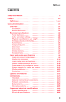 3
3 -
 4
4 -
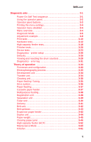 5
5 -
 6
6 -
 7
7 -
8
-
9
-
10
-
11
-
12
-
13
-
14
-
15
-
16
-
17
-
18
-
19
-
20
-
21
-
22
-
23
-
24
-
25
-
26
-
27
-
28
-
29
-
30
-
31
-
32
-
33
-
34
-
35
-
36
-
37
-
38
-
39
-
40
-
41
-
42
-
43
-
44
-
45
-
46
-
47
-
48
-
49
-
50
-
51
-
52
-
53
-
54
-
55
-
56
-
57
-
58
-
59
-
60
-
61
-
62
-
63
-
64
-
65
-
66
-
67
-
68
-
69
-
70
-
71
-
72
-
73
-
74
-
75
-
76
-
77
-
78
-
79
-
80
-
81
-
82
-
83
-
84
-
85
-
86
-
87
-
88
-
89
-
90
-
91
-
92
-
93
-
94
-
95
-
96
-
97
-
98
-
99
-
100
-
101
-
102
-
103
-
104
-
105
-
106
-
107
-
108
-
109
-
110
-
111
-
112
-
113
-
114
-
115
-
116
-
117
-
118
-
119
-
120
-
121
-
122
-
123
-
124
-
125
-
126
-
127
-
128
-
129
-
130
-
131
-
132
-
133
-
134
-
135
-
136
-
137
-
138
-
139
-
140
-
141
-
142
-
143
-
144
-
145
-
146
-
147
-
148
-
149
-
150
-
151
-
152
-
153
-
154
-
155
-
156
-
157
-
158
-
159
-
160
-
161
-
162
-
163
-
164
-
165
-
166
-
167
-
168
-
169
-
170
-
171
-
172
-
173
-
174
-
175
-
176
-
177
-
178
-
179
-
180
-
181
-
182
-
183
-
184
-
185
-
186
-
187
-
188
-
189
-
190
-
191
-
192
-
193
-
194
-
195
-
196
-
197
-
198
-
199
-
200
-
201
-
202
-
203
-
204
-
205
-
206
-
207
-
208
-
209
-
210
-
211
-
212
-
213
-
214
-
215
-
216
-
217
-
218
-
219
-
220
-
221
-
222
-
223
-
224
-
225
-
226
-
227
-
228
-
229
-
230
-
231
-
232
-
233
-
234
-
235
-
236
-
237
-
238
-
239
-
240
-
241
-
242
-
243
-
244
-
245
-
246
-
247
-
248
-
249
-
250
-
251
-
252
-
253
-
254
-
255
-
256
-
257
-
258
-
259
-
260
-
261
-
262
-
263
-
264
-
265
-
266
-
267
-
268
-
269
-
270
-
271
-
272
-
273
-
274
-
275
-
276
-
277
-
278
-
279
-
280
-
281
-
282
-
283
-
284
-
285
-
286
-
287
-
288
-
289
-
290
-
291
-
292
-
293
-
294
-
295
-
296
-
297
-
298
-
299
-
300
-
301
-
302
-
303
-
304
-
305
-
306
-
307
-
308
-
309
-
310
-
311
-
312
-
313
-
314
-
315
-
316
-
317
-
318
-
319
-
320
-
321
-
322
-
323
-
324
-
325
-
326
-
327
-
328
-
329
-
330
-
331
-
332
-
333
-
334
-
335
-
336
-
337
-
338
-
339
-
340
-
341
-
342
-
343
-
344
-
345
-
346
-
347
-
348
-
349
-
350
-
351
-
352
-
353
-
354
-
355
-
356
-
357
-
358
-
359
-
360
-
361
-
362
-
363
-
364
-
365
-
366
-
367
-
368
-
369
-
370
-
371
-
372
-
373
-
374
-
375
-
376
-
377
-
378
-
379
-
380
-
381
-
382
-
383
-
384
-
385
-
386
-
387
-
388
-
389
-
390
-
391
-
392
-
393
-
394
-
395
-
396
-
397
-
398
-
399
-
400
-
401
-
402
-
403
-
404
-
405
-
406
-
407
-
408
-
409
-
410
-
411
-
412
-
413
-
414
-
415
-
416
-
417
-
418
-
419
-
420
-
421
-
422
-
423
-
424
-
425
-
426
-
427
-
428
-
429
-
430
-
431
-
432
-
433
-
434
-
435
-
436
-
437
-
438
-
439
-
440
-
441
-
442
-
443
-
444
-
445
-
446
-
447
-
448
-
449
-
450
-
451
-
452
-
453
-
454
-
455
-
456
-
457
-
458
-
459
-
460
-
461
-
462
-
463
-
464
-
465
-
466
-
467
-
468
-
469
-
470
-
471
-
472
-
473
-
474
-
475
-
476
-
477
-
478
-
479
-
480
-
481
-
482
-
483
-
484
-
485
-
486
-
487
-
488
-
489
-
490
-
491
-
492
 |
 |

5055-xxx
Lexmark C91x
Lexmark and Lexmark with diamond
design are trademarks of Lexmark
International, Inc., registered in the
United States and/or other countries.
• Table of Contents
• Index
• Safety and Notices
• Trademarks
• Start Diagnostics
Revised
October
17
, 2006