LiftMaster 8557 8557 Manual
LiftMaster 8557 Manual
 |
View all LiftMaster 8557 manuals
Add to My Manuals
Save this manual to your list of manuals |
LiftMaster 8557 manual content summary:
- LiftMaster 8557 | 8557 Manual - Page 1
ELITE Series Garage Door Opener Models • 8550 - DC Belt Drive with Battery Backup • 8557 - 3/4 hp Belt Drive FOR RESIDENTIAL USE ONLY ■ Please read this manual and the enclosed safety materials carefully! ■ Fasten the manual near the garage door after installation. ■ The door WILL NOT CLOSE unless - LiftMaster 8557 | 8557 Manual - Page 2
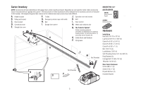
Preparation Safety Symbol and Signal Word Review This garage door opener has been designed and tested to offer safe service provided it is installed, operated, maintained and tested in strict accordance with the instructions and warnings contained in this manual. When you see these Safety Symbols - LiftMaster 8557 | 8557 Manual - Page 3
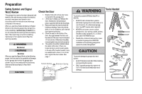
different. A. Header bracket B. Pulley and bracket C. Door bracket D. Curved door arm E. Straight door arm A B F. Trolley G. Emergency release rope and handle H. Rail I. Garage door opener CF K G D E J. Sprocket cover and screws K. Belt L. Door control M. White and red/white wire N. The - LiftMaster 8557 | 8557 Manual - Page 4
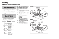
the two bolts from the top of the garage door opener. 1.2 Align the rail and the styrofoam over the sprocket. Cut the tape from the rail, belt, and styrofoam. 1.3 Model 8550: Fasten the rail with the previously removed bolts. Model 8557: Fasten the rail with the previously removed washer bolt and - LiftMaster 8557 | 8557 Manual - Page 5
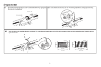
and brace it firmly against the trolley. the trolley. Do not use any tools. (To motor unit) Spring Trolley Nut Nut ring slot 2.3 Tighten the spring trolley nut with an adjustable wrench or a 7/16" open end wrench about a quarter turn until the spring releases and snaps the nut ring against the - LiftMaster 8557 | 8557 Manual - Page 6
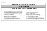
connect garage door opener to power source until instructed to do so. 8. NEVER wear watches, rings or loose clothing while installing or servicing opener. They could be caught in garage door or opener mechanisms. 9. Install wall-mounted garage door control: • within sight of the garage door. • out - LiftMaster 8557 | 8557 Manual - Page 7
To be enabled ONLY when operating a sectional door. NOTE: If you are installing the garage door opener on a one-piece door, visit www.liftmaster.com for installation instructions. 1.1 Close the door and mark the inside vertical centerline of the garage door. 1.2 Extend the line onto the header wall - LiftMaster 8557 | 8557 Manual - Page 8
attach the header bracket either to the wall above the garage door, or to the ceiling. Follow the instructions which will work best for your particular requirements. Do not install the header bracket over drywall. If installing into masonry, use concrete anchors (not provided). HARDWARE Lag Screw - LiftMaster 8557 | 8557 Manual - Page 9
open the door and place a 2x4 (laid flat) under the rail. NOTE: If the door hits the trolley when it is raised, pull the trolley release arm down to disconnect the inner and outer trolley. Slide the outer trolley toward the garage door opener. The trolley can remain disconnected until instructed - LiftMaster 8557 | 8557 Manual - Page 10
to structural supports before installing the opener. This bracket and fastening hardware are not provided. Instructions below are for attaching the garage door opener directly to structural supports. 5.1 Measure the distance from each side of the motor unit to the structural support. 5.2 Cut both - LiftMaster 8557 | 8557 Manual - Page 11
use short neck or specialty light bulbs. performance of your remote control(s). 6.3 Rotate the lens up to close. 7 Attach the emergency release rope and handle To prevent possible SERIOUS INJURY or DEATH from a falling garage door: • If possible, use emergency release handle to disengage trolley - LiftMaster 8557 | 8557 Manual - Page 12
brace. For the vertical brace, 2 pieces of angle iron are used to create a U-shaped support. The best solution is to check with your garage door manufacturer for an opener installation door reinforcement kit. NOTE: Many door reinforcement kits provide for direct attachment of the clevis pin and - LiftMaster 8557 | 8557 Manual - Page 13
The bolts, nuts and lock washers. trolley will re-engage automatically when the garage door opener is activated. Nut 5/16" - 18 Lock Washer 5/16" Hex Bolt 5/16" - 18 x 7/8" If the straight door arm is hanging down too far, you may cut 6 inches (15 cm) from the solid end. Trolley release arm 13 - LiftMaster 8557 | 8557 Manual - Page 14
is NOT connected BEFORE installing door control. • Connect ONLY to 12 VOLT low voltage wires. accessories, see page 37. Your garage door opener is compatible with up to 2 Smart Control Panels or 4 of any other Security+ 2.0™ door controls. NOTE: Older LiftMaster door controls To prevent possible - LiftMaster 8557 | 8557 Manual - Page 15
on the garage door opener. To insert or release wires from the terminal, push in the tab with screwdriver tip. RED WHITE WHITE GREY PRE-WIRED INSTALLATIONS: When wiring the door control to the garage door opener make sure you use the same wires that are connected to the door control. Staple 15 - LiftMaster 8557 | 8557 Manual - Page 16
Install the Door Control 3 Attach the warning labels 3.1 Attach the entrapment warning label on the wall near the door control with tacks or staples. 3.2 Attach the manual release/safety reverse test label in a visible location on the inside of the garage door. 16 - LiftMaster 8557 | 8557 Manual - Page 17
MUST NOT be disabled. • Install the safety reversing sensor so beam is NO HIGHER than 6" (15 cm) above garage floor. IMPORTANT INFORMATION ABOUT THE SAFETY REVERSING SENSORS The safety reversing sensors must be connected and aligned correctly before the garage door opener will move in the down - LiftMaster 8557 | 8557 Manual - Page 18
track, the wall, or the floor. If the door track will not support the sensor bracket a wall installation is recommended. Choose one of the following installations. HARDWARE Carriage Bolt 1/4"-20x1/2" OPTION A DOOR TRACK INSTALLATION 1.1A Slide the curved arms of the sensor bracket around the - LiftMaster 8557 | 8557 Manual - Page 19
Nut 1/4" - 20 2 Wire the Safety Reversing Sensors OPTION A INSTALLATION WITHOUT PRE-WIRING PRE-WIRED INSTALLATIONS: If your garage 2.1A Run the wire from both sensors to the already has wires installed for the safety reversing garage door opener. Attach the wire to sensors, see page 20. the - LiftMaster 8557 | 8557 Manual - Page 20
to the purple wire. Not Provided White Yellow (for example) White/Black Safety reversing sensor wires Purple (for example) Pre-installed wires 2.4B At the garage door opener, strip 7/16 inch (11 mm) of insulation from each end of the wires previously chosen for the safety reversing sensors - LiftMaster 8557 | 8557 Manual - Page 21
so that wire does not come in contact with moving parts. 1.10B Reinstall the cover. DO NOT run garage door opener at this time. Wiring through a terminal block (8550 models manufactured after April 12, 2013 and all 8557 models): 1.1B Remove the motor unit cover screws and set the cover aside. 1.2B - LiftMaster 8557 | 8557 Manual - Page 22
THE SENDING SENSOR IS NOT GLOWING: Make sure there is power to the garage door opener. Make sure the sensor wire is not shorted/broken. Make sure the WHITE GREY 3 Ensure the Door Control is wired correctly If the door control has been installed and wired correctly a message will display on the - LiftMaster 8557 | 8557 Manual - Page 23
instructional video on programming your new garage door opener use your smartphone to read the QR Code below: To prevent damage to vehicles, be sure fully open door provides adequate clearance. PROGRAMMING BUTTONS The programming buttons are located on the left side panel of the garage door opener - LiftMaster 8557 | 8557 Manual - Page 24
If the garage door opener lights are flashing 10 times during the steps for Program the Travel, the safety reversing sensors are misaligned or obstructed (refer to page 22). When the sensors are aligned and unobstructed, cycle the door through a complete up and down cycle using the remote control or - LiftMaster 8557 | 8557 Manual - Page 25
3.1 Open the door. Place the garage door opener carton in the path of the door. Without a properly installed safety reversing sensor, persons (particularly small children) could be SERIOUSLY INJURED or KILLED by a closing garage door. 3.2 Press the remote control push button to close the door. The - LiftMaster 8557 | 8557 Manual - Page 26
ALL electric and battery power BEFORE performing ANY service or maintenance. • Use ONLY LiftMaster part # 485LM for replacement battery. • DO NOT dispose of battery in fire. Battery may explode. Check with local codes for disposal instructions. 1.1 Unplug the garage door opener. 1.2 Open the light - LiftMaster 8557 | 8557 Manual - Page 27
When the garage door opener is in battery every 30 seconds, indicates the battery is low. backup mode the garage door opener lights, RED LED: Timer-to-Close, and Remote Close features are The garage door opener's 12V battery needs to be unavailable. replaced. * If applicable, part number 485LM - LiftMaster 8557 | 8557 Manual - Page 28
INJURY or DEATH: 1. READ AND FOLLOW ALL WARNINGS AND INSTRUCTIONS. 2. ALWAYS keep remote controls out of reach of children. NEVER permit children to operate or play with garage door control push buttons or remote controls. 3. ONLY activate garage door when it can be seen clearly, it is properly - LiftMaster 8557 | 8557 Manual - Page 29
the button on the door control or keyless entry until the door is fully closed. The safety reversing sensors do not affect the opening cycle. The safety reversing sensor must be connected and aligned correctly before the garage door opener will move in the down direction. BATTERY BACKUP* The battery - LiftMaster 8557 | 8557 Manual - Page 30
. If there is a problem with the garage door opener the screen will display the Diagnostic Code. Refer to the Troubleshooting section. The following features are accessible through the screen using the navigation buttons: LEARN A DEVICE Any compatible remote controls, wireless keyless entry, or - LiftMaster 8557 | 8557 Manual - Page 31
currently programmed to operate the garage door opener. PROGRAM: Add remote controls, MyQ® devices, an extra remote button to control your garage door CONTRAST: Adjust the contrast of the screen. opener lights, or a keyless entry. DISPLAY ERROR: Displays any errors that have occurred. To program - LiftMaster 8557 | 8557 Manual - Page 32
with your garage door opener. Older LiftMaster remote controls are NOT compatible, see page 37 for compatible accessories. Programming can be done through the door control or the learn button the garage door opener. To program additional accessories refer to the instructions provided with the - LiftMaster 8557 | 8557 Manual - Page 33
button on the remote control... The garage door opener will activate. To Erase the Memory ERASE ALL REMOTE CONTROLS AND KEYLESS ENTRIES 1 Press and hold the learn button on garage door opener until the learn LED goes out (approximately 6 seconds). All remote control and keyless entry codes - LiftMaster 8557 | 8557 Manual - Page 34
see page 25. THE REMOTE CONTROL BATTERY EVERY YEAR • Oil door rollers, bearings and hinges. The garage door opener does not require additional lubrication. Do not grease the door tracks. • Test the battery and consider replacing the battery to ensure the garage door opener will operate during an - LiftMaster 8557 | 8557 Manual - Page 35
spring or door lock, correct as needed. Replace motor if necessary. Program travel to coasting position or have door balanced by a trained technician. Replace logic board. Check travel module for proper assembly, replace if necessary. Battery backup charging circuit error, replace logic board. *(if - LiftMaster 8557 | 8557 Manual - Page 36
from your garage door opener and reprogram the remote control(s). The LEDs on the door control blink: If you have a Smart Control Panel installed and the TTC is set to a custom time, press the ON button on the Premium Motion-Detecting Control Panel to set the time properly. My vehicle's Homelink® is - LiftMaster 8557 | 8557 Manual - Page 37
. 892LT/894LT 2 & 4 Button Learning Remote Controls: Compatible with LiftMaster® garage door openers manufactured since 1997. Also compatible with Encrypted DIP for gate applications. 485LM 12V Battery for Backup System: Provides backup power to the garage door opener (if applicable). 37 - LiftMaster 8557 | 8557 Manual - Page 38
(E.G., BATTERIES IN REMOTE CONTROL TRANSMITTERS AND LIGHT BULBS), OR UNITS INSTALLED FOR NON-RESIDENTIAL USE. THIS LIMITED WARRANTY DOES NOT COVER ANY PROBLEMS WITH, OR RELATING TO, THE GARAGE DOOR OR GARAGE DOOR HARDWARE, INCLUDING BUT NOT LIMITED TO THE DOOR SPRINGS, DOOR ROLLERS, DOOR ALIGNMENT - LiftMaster 8557 | 8557 Manual - Page 39
Trolley Assembly 6 Tensioner Assembly 7 Trolley Threaded Shaft Not Shown Owner's Manual Part Number 41A5434-11 41A5434-13 41A5434-14 41B5424 4A1008 2777BD 2778BD 2770BD 41B3869-3A 41B4103 109B48 114A4665 3 6 2 4 7 5 1 Installation Parts Description Part Number 1 Curved Door Arm 178B35 2 Door - LiftMaster 8557 | 8557 Manual - Page 40
Repair Parts Garage Door Opener Parts - MODEL 8550 1 11 9 4 3 12b 12a 10 8 7 5 2 4 3 6 40 Description 1 Sprocket and Sprocket Cover with Screws 2 End Panel with battery cover and light socket 3 Light Lens 4 Light Socket 5 Transformer 6 Cover 7 Motor and Travel Module 8 Travel Module 9 End - LiftMaster 8557 | 8557 Manual - Page 41
Repair Parts Garage Door Opener Parts - MODEL 8557 4 5 1 2 3 15 14 7 6 10 9 12 11 8 13 6 7 114A4665 © 2013, The Chamberlain Group, Inc. All Rights Reserved DESCRIPTION 1 Cover with screws 2 Gear and sprocket 3 Drive and Worm Gear 4 Line Cord 5 End panel 6 Light Socket 7 Light Lens 8 - LiftMaster 8557 | 8557 Manual - Page 42
Ouvre-porte de garage Série ELITE Modéles • 8550 - À courroie à CC avec pile de seccours • 8557 - 3/4 hp à courroie POUR RÉSIDENCES SEULEMENT ■ Lire attentivement ce manuel ainsi que les consignes de sécurité! ■ Après la pose, accrocher ce manuel près de la porte de garage pour s'y reporter ulté - LiftMaster 8557 | 8557 Manual - Page 43
garage a été conçu et mis à l'essai dans le but d'offrir un service sûr à condition qu'il soit installé, utilisé, entretenu et mis à l'essai en stricte conformité avec les instructions de torsion ou une plaque d'appui centrale dans le chemin du support de linteau, il peut être posé à moins de 1,2 - LiftMaster 8557 | 8557 Manual - Page 44
fixé (2) O. Documentation et étiquettes de sécurité P. Graisse sur le rail L M Non Fournis J N Non Fournis P O SECURITY✚ 2.0™ ACCESSORIES 880LM Smart Control Panel® 895MAX Télécommande 829LM Moniteur de porte de garage Matériel Installation Vis hexagonale de 5/16 po-18 x 7/8 po (4) Tire-fond - LiftMaster 8557 | 8557 Manual - Page 45
et de la mousse de polystyrène. 1.3 Modèle 8550 : Fixez le rail avec les boulons retirés précédemment. Modèle 8557 : Fixez le rail avec le boulon et contreécrou retirés précédemment. 1.4 Placer la courroie au-dessus le pignon du ouvre-porte de garage. 1.5 Fixez le carter de pignon sur le pignon de - LiftMaster 8557 | 8557 Manual - Page 46
2 Serrage de la courroie 2.1 A la main, visser l'écrou à ressort du chariot sur l'arbre fileté jusqu'à ce qu'il soit serré contre le chariot. Ne pas utiliser d'outils. (Vers Tête de puissance) 2.2 Insérez la pointe d'un tournevis plat dans l'une des fentes pour bague et la tenir fermement contre le - LiftMaster 8557 | 8557 Manual - Page 47
si vous utilisez une porte de garage monobloc ou battante. Elle doit être activée UNIQUEMENT lorsqu'on utilise une porte articulée. REMARQUE : Si vous installez l'ouvre-porte de garage sur une porte monobloc, consultez le site www.liftmaster.com pour obtenir les instructions d'installation. 6 - LiftMaster 8557 | 8557 Manual - Page 48
, consultez le site www.liftmaster.com pour obtenir les instructions d'installation. 1.1 Fermez la porte et marquez l'axe vertical intérieur de la porte du garage. 1.2 Prolongez cet axe sur le linteau, au-dessus de la porte. N'oubliez pas que l'on ne peut fixer le support du linteau à moins de - LiftMaster 8557 | 8557 Manual - Page 49
mur en option Point de course le plus haut (de la porte du garage) (Linteau) Support de linteau OPTION B INSTALLATION AU PLAFOND 2.1B Prolonger l'axe vertical sur le plafond, comme illustré. 2.2B Centrer le support sur l'axe vertical à 15 cm (6 po) au maximum du mur. S'assurer que la flèche est - LiftMaster 8557 | 8557 Manual - Page 50
3 Fixation du rail sur le support de linteau 3.1 Alignement du rail sur le support de linteau. Insérez l'axe de chape dans les trous du support de linteau et du rail. Fixez-le avec un anneau d'arrêt. REMARQUE : Utilisez une des boîtes d'emballage pour protéger l'ouvre-porte de garage. Anneau d'arr - LiftMaster 8557 | 8557 Manual - Page 51
pas fournies. Les instructions ci-dessous indiquent comment attacher votre ouvre-porte de garage directement à des support de structures. 5.1 4. Faire fonctionner la porte manuellement. Si la porte frappe le rail, lever le support de linteau. REMARQUE : NE PAS mettre l'ouvre-porte sous tension - LiftMaster 8557 | 8557 Manual - Page 52
: • Si possible, utilisez la poignée de déclenchement d'urgence pour dégager le chariot UNIQUEMENT lorsque la porte de garage est FERMÉE. Des ressorts faibles ou brisés ou une porte déséquilibrée peuvent provoquer la chute rapide et/ou imprévue d'une porte ouverte. • N'utilisez JAMAIS - LiftMaster 8557 | 8557 Manual - Page 53
INSTALLATION 8 Fixation du support de linteau Un renfort horizontal et vertical est nécessaire pour les portes de garage légères support en forme de U. La meilleure solution consiste à s'adresser au fabricant de la porte de garage pour obtenir un nécessaire de MATÉRIEL Vis autotaraudeuse 1/4 po-14 - LiftMaster 8557 | 8557 Manual - Page 54
êt Axe de chape 5/16 po x 1 po 9.3 Fixez la biellette courbée sur le support de porte à l'aide d'un axe de chape. Fixez-la avec un anneau d'arrêt. ée de déverrouillage de secours vers l'ouvre-porte de garage de façon à ce que la biellette de dé 15 cm) du bout. Biellette de dégagement du chariot 13 - LiftMaster 8557 | 8557 Manual - Page 55
installer la commande de la porte. panneaux Smart Control ou 4 commandes de • Raccorder UNIQUEMENT à des fils basse tension de 12 V. porte Security+ 2.0™. REMARQUE : Les Pour prévenir d'éventuelles BLESSURES GRAVES ou LA MORT par suite d'une porte de garage anciens commandes de porte LiftMaster - LiftMaster 8557 | 8557 Manual - Page 56
l'ouvre-porte de garage MATÉRIEL Agrafe isolée (Non illustr garage. Fixer le fil au mur et au plafond avec des agrafes (cette procédure ne s'applique pas à la boîte simple ou aux installations INSTALLATIONS PRÉCÂBLÉES : Lors du raccordement des fils de la commande de porte à l'ouvre-porte de garage - LiftMaster 8557 | 8557 Manual - Page 57
des punaises ou des agrafes. 3.2 Placer l'étiquette concernant l'essai d'inversion de sécurité/ouverture manuelle bien en vue sur le côté intérieur de la porte de garage. 16 - LiftMaster 8557 | 8557 Manual - Page 58
suivants : • Les capteurs sont installés à l'intérieur du garage, un de chaque côté de la porte. • Les capteurs sont face à face avec les lentilles alignées et la lentille du détecteur de réception ne reçoit pas de lumière directe du soleil. • Les capteurs sont pas plus de 15 cm (6 po) au-dessus - LiftMaster 8557 | 8557 Manual - Page 59
inversion de sécurité peuvent être fixés au guide de porte, au mur ou au sol. Si votre guide de porte ne supporte pas solidement le support de capteur, une pose murale est recommandée. Choisir l'une des installations suivantes. OPTION A INSTALLATION DES GUIDES DE PORTE MATÉRIEL Boulon à tête bomb - LiftMaster 8557 | 8557 Manual - Page 60
obstruée par le support de capteur. Écrou à oreilles de 1/4 po-20 2 Câblage des capteurs d'inversion de sécurité OPTION A INSTALLATION SANS CÂBLES PRÉINSTALLÉS INSTALLATIONS PRÉCÂBLÉES : Si des câbles pour les capteurs de l'inverseur de sécurité sont déjà installés dans votre garage, voir page 20 - LiftMaster 8557 | 8557 Manual - Page 61
Fournis Blanc Jaune (par exemple) Blanc / Noir Câbles du capteur de l'inverseur de sécurité Violet (par exemple) Câbles préinstallés 2.4B Au niveau de l'ouvre-porte de garage, enlever 11 mm (7/16 po) d'isolation de chaque extrémité des fils choisis précédemment pour les capteurs d'inversion de - LiftMaster 8557 | 8557 Manual - Page 62
fonctionner l'ouvre-porte de garage pour le moment. OPTION B CÂBLAGE PERMANENT Si les codes municipaux exigent une installation électrique permanente, proc -porte de garage pour le moment. Câblage à un bornier à vis (Modèles 8550 construits après le avril 12, 2013 et tout les modèles 8557) : 1.1B - LiftMaster 8557 | 8557 Manual - Page 63
curité La porte ne se fermera pas si les détecteurs n'ont pas été installés et alignés correctement. 2.1 Assurez-vous que les témoins DEL des deux celle-ci va revenir en arrière et les lumières de l'ouvre-porte de garage vont clignoter dix fois. Si la porte est déjà ouverte, elle ne se fermera pas - LiftMaster 8557 | 8557 Manual - Page 64
Si quoi que ce soit gêne la fermeture de la porte, elle remontera. Pour observer un vidéo d'instruction court sur programmer votre nouvel ouvre porte de garage employez votre smartphone pour lire le code de QR ci-dessous : Pour prévenir les dommages aux véhicules, s'assurer que la porte entièrement - LiftMaster 8557 | 8557 Manual - Page 65
Sans un système d'inversion de sécurité bien installé, des personnes (plus particulièrement les petits enfants) pourraient être GRIÈVEMENT BLESSÉES ou TUÉES par une porte de garage qui se referme. • Un réglage erroné des courses de la porte de garage gênera un fonctionnement approprié du système - LiftMaster 8557 | 8557 Manual - Page 66
La porte de garage DOIT remonter au garage. de garage l'essai installé, des personnes (plus particulièrement les petits enfants) pourraient être GRIÈVEMENT BLESSÉES ou TUÉES par une porte de garage garage garage clignotera 10 fois. détecteur est mal aligné ou obstrué). Si l'ouvre-porte de garage - LiftMaster 8557 | 8557 Manual - Page 67
LiftMaster nº 485LM pour remplacer la pile. • Ne jetez PAS la pile dans le feu. La pile peut exploser. Pour connaître les instructions relatives à son élimination, vérifiez les codes pile est de 24 heures. Statut de batterie DEL 2.3 Branchez l'ouvre-porte de garage. Vérifiez si le témoin DEL de la - LiftMaster 8557 | 8557 Manual - Page 68
tension de 12 V c.c. à l'ouvre- que la pile est en cours de recharge. porte de garage pendant une garage a perdu l'alimentation La pile durera durera environ un à deux ans pour électrique et est en mode d'alimentation par pile un usage normal. Les instructions de de secours. Statut de batterie - LiftMaster 8557 | 8557 Manual - Page 69
TOUTES LES INSTRUCTIONS. 2. GARAGE BIEN ÉQUILIBRÉE (voir la page 2). Une porte mal équilibrée peut ne PAS inverser sa course en cas de besoin et peut entraîner des BLESSURES GRAVES, voire MORTELLES. 12 intervention. 14. Ce 15. N'activez PAS la minuterie de fermeture si vous utilisez une porte de garage - LiftMaster 8557 | 8557 Manual - Page 70
MyQ® et Security+ 2.0™, voir le page 37. REMARQUE : Les anciens telecommandes, commandes de porte LiftMaster, et les produits de tiers ne son pas compatibles. Accessories SECURITY+ 2.0TM CAPACITÉ DE MISE EN MÉMOIRE Télécommandes Jusqu'à 40 Commandes de porte Jusqu'à 2 panneaux Smart Control - LiftMaster 8557 | 8557 Manual - Page 71
S'il y a un problème avec l'ouvre-porte de garage, l'écran affichera le code de diagnostic. Se reporter au chapitre Dépannage. Les fonctions suivantes fermeture de la porte. Une commande de télédéverrouillage doit être installée dans le cas d'un verrouillage accidentel lors de l'utilisation de - LiftMaster 8557 | 8557 Manual - Page 72
de la Smart Control Panel Les fonctions le menu Service (entretien). Touches de navigation RÉGLAGE DE L'HEURE : Régler l'heure, choisir un horaire de 12 ou 24 MyQ®, de commandes de porte et de commandes de télédéverrouillage actuellement programmés pour faire fonctionner l'ouvre-porte de garage - LiftMaster 8557 | 8557 Manual - Page 73
du bouton d'apprentissage de l'ouvre-porte de garage. Pour programmer des accessoires supplémentaires, consultez les instructions qui accompagnent l'accessoire en question ou allez sur www.liftmaster.com. Si votre véhicule est équipé du système Homelink®, un adaptateur externe peut être nécessaire - LiftMaster 8557 | 8557 Manual - Page 74
LES TÉLÉCOMMANDES ET LES COMMANDES DE TÉLÉDÉVERROUILLAGE 1 Appuyer sur le bouton Learn de l'ouvre-porte de garage et le maintenir enfoncé jusqu'à ce que le témoin DEL du bouton Learn s'éteigne (environ 6 secondes). Tous les codes de la télécommande et de la commande de télédéverrouillage et sont - LiftMaster 8557 | 8557 Manual - Page 75
guides de la porte. • Mettre la pile à l'essai et songer à la remplacer pour s'assurer que la porte de garage fonctionnera pendant une panne de courant électrique, voir page 26 pour mise a l'essai de la pile. TOUS LES DEUX OU TROIS ANS • Utiliser un chiffon pour éliminer la graisse sur le rail 15 du - LiftMaster 8557 | 8557 Manual - Page 76
garage font clignoter les codes d'anomalie. CODE D'ANOMALIE SYMPTÔME SOLUTION La flèche vers le haut La flèche vers le bas clignote clignote 1 1 L'ouvre-porte de garage ne ferme pas la porte et l'éclairage Les détecteurs inverseurs de sécurité ne sont pas install une distance de 15 à 20 cm - LiftMaster 8557 | 8557 Manual - Page 77
31. La télécommande de mon voisin ouvre ma porte de garage : Effacer la mémoire de votre ouvre-porte de garage et reprogrammer la ou les télécommandes. Les DEL de la commande de porte clignotent : Si vous avez un panneau Smart Control installé et que la minuterie de fermeture est réglée à une heure - LiftMaster 8557 | 8557 Manual - Page 78
+ 2.0™. Parasurtenseur : 893MAX Le parasurtenseur d'ouvre-porte de garage a été conçu pour protéger les ouvre-porte de garage LiftMaster® contre les dommages causés par la foudre et les surtensions. Facile à installer. Émetteur à code sans fil MAX : 890MAX Pour une utilisation à l'ext - LiftMaster 8557 | 8557 Manual - Page 79
, avant de démonter le produit. Des instructions de démontage et d'expédition vous seront UNITÉS INSTALLÉES POUR UNE UTILISATION NON RÉSIDENTIELLE.LA PRÉSENTE GARANTIE LIMITÉE NE COUVRE PAS LES PROBLÈMES RELATIFS OU CONNEXES À LA PORTE DU GARAGE OU À LA QUINCAILLERIE DE LA PORTE DU GARAGE - LiftMaster 8557 | 8557 Manual - Page 80
porte de 10 pi 41A5434-14 2 Support de poulie de courroie 41B5424 3 Maillon principal 4A1008 4 Rail monobloc 2.1 m (7 pi) 2777BD Rail monobloc 2.4 m (8 pi) Rail monobloc 3 m (10 pi)) 5 Chariot 6 Tendeur 7 Arbre fileté du chariot Non illustrés Manuel d'instructions 2778BD 2770BD 41B3869-3A - LiftMaster 8557 | 8557 Manual - Page 81
Pièces de rechange Pièces de l'ouvre-porte de garage - MODÉLE 8550 1 11 9 4 3 12b 12a 10 8 7 5 2 4 3 6 40 Description du récepteur 45DCT 11a Cordon électrique (Modèles construits avant le avril 12, 2013) 41B135 11b Cordon électrique (Modèles construits après le avril 12, 2013) 41B4245 - LiftMaster 8557 | 8557 Manual - Page 82
rechange Pièces de l'ouvre-porte de garage - MODÉLE 8557 1 2 3 4 5 15 14 7 6 10 9 12 11 8 13 6 7 114A4665 © installation et l'entretien, appelez le : 1-800-528-9131 Sinon, rendez-vousau site Web : www.liftmaster.com Avant d'appeler, ayezle numéro de modèle de l'ouvre-porte de garage
-
 1
1 -
 2
2 -
 3
3 -
 4
4 -
 5
5 -
 6
6 -
 7
7 -
8
-
9
-
10
-
11
-
12
-
13
-
14
-
15
-
16
-
17
-
18
-
19
-
20
-
21
-
22
-
23
-
24
-
25
-
26
-
27
-
28
-
29
-
30
-
31
-
32
-
33
-
34
-
35
-
36
-
37
-
38
-
39
-
40
-
41
-
42
-
43
-
44
-
45
-
46
-
47
-
48
-
49
-
50
-
51
-
52
-
53
-
54
-
55
-
56
-
57
-
58
-
59
-
60
-
61
-
62
-
63
-
64
-
65
-
66
-
67
-
68
-
69
-
70
-
71
-
72
-
73
-
74
-
75
-
76
-
77
-
78
-
79
-
80
-
81
-
82
 |
 |
CONTENTS
Preparation. . . . . . . . . . . . . . . .2-3
Assembly
. . . . . . . . . . . . . . . . .4-5
Installation . . . . . . . . . . . . . . .6-13
Install the Door Control . . . . . . 14-16
Install the Protector System
®
. . 17-20
Power. . . . . . . . . . . . . . . . . . 21-22
Adjustments
. . . . . . . . . . . . . 23-25
Battery Backup* . . . . . . . . . . . 26-27
Operation . . . . . . . . . . . . . . . . . 28
Features . . . . . . . . . . . . . . . . . . 29
Door Control
. . . . . . . . . . . . . 30-31
Remote Control . . . . . . . . . . . 32-33
To Erase the Memory
. . . . . . . . . 33
To Open the Door Manually . . . . . 34
Maintenance . . . . . . . . . . . . . . . 34
Troubleshooting. . . . . . . . . . . 35-36
Accessories. . . . . . . . . . . . . . . . 37
Warranty. . . . . . . . . . . . . . . . . . 38
Repair Parts
. . . . . . . . . . . . . 39-41
* If applicable
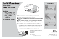
ELITE Series
Garage Door Opener
The Chamberlain Group, Inc.
845 Larch Avenue
Elmhurst, Illinois 60126-1196
■
Please read this manual and the enclosed safety materials carefully!
■
Fasten the manual near the garage door after installation.
■
The door WILL NOT CLOSE unless the Protector System
®
is connected and properly
aligned.
■
Periodic checks of the garage door opener are required to ensure safe operation.
■
The model number label is located on the left side panel of your garage door opener.
■
This garage door opener is ONLY compatible with MyQ
®
and Security
✚
2.0™
accessories.
■
DO NOT enable the Timer-to-Close feature if you are installing the garage door
opener on a one-piece door. The Timer-to-Close is to be used ONLY with
sectional doors.
NOTE:
If you are installing the garage door opener on a one-piece door, visit
www.liftmaster.com for installation instructions.
www.liftmaster.com
Serial Number:
Date of Purchase:
Models
•
8550 - DC Belt Drive
with Battery Backup
•
8557 - 3/4 hp
Belt Drive
FOR RESIDENTIAL USE ONLY
.
Write down the following information for
future reference: