LiftMaster CAPXLV LiftMaster K-41-0117-000 Instruction Sheet - English French - Page 2
Firmware Update - capxl key
 |
View all LiftMaster CAPXLV manuals
Add to My Manuals
Save this manual to your list of manuals |
Page 2 highlights
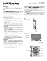
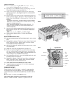
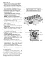
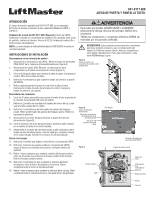
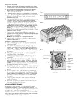
Replace the faceplate 17. Remove 4 locknuts securing the CAPXL door in place. Carefully remove old door/display assembly from enclosure. 18. Open hinge on new CAPXL door/display assembly. Align and insert hinge studs through enclosure mounting holes. 19. Install 4 lock nuts onto hinge studs while observing CAPXL door alignment to enclosure, adjusting door alignment as needed before fully tightening. 20. Reinstall existing parts (Camera bracket, Card Reader Bracket/Cover, Postal Lock Cover, Speaker, Microphone*, Postal Lock Switch, Light Sensor Board, Control Board) in reverse order from which they were removed. *Use special care to ensure microphone boot is properly sealed to CAPXL door. Leaks could allow water to enter the chassis causing touchscreen display malfunction. NOTE: Take special care when inserting display data cable. The connector is keyed with the two notches at the topmost part of connector (Figure D). 21. Remove dummy plug from upper/leftmost USB socket on control board (Figure E) and plug new touch panel encoder cable into the USB socket. NOTE: Avoid using blue USB 3.0 socket (Bottom/Right). 22. Secure cables to display bracket in 3 places using cable ties (Figure F). Replace the Power/Internet board 23. Remove 6 screws securing the Power/Internet plastic board cover in place. 24. Unplug Audio In, Speaker, Postal Lock, Sensor Board, Control board power, USB, Door1, Door2, Ethernet IN/OUT, and Radio antenna coax (if used) from Power/Internet board. 25. Remove 6 hex stand-offs securing the Power/Internet board in place and remove board. 26. Install new Power/Internet board using 6 hex stand-offs. 27. Route new display backlight cable around wiring harness and plug into new Power and Internet board "OTS Backlit" connector at top mid-section of board. (Figure B) NOTE: Power/Internet plastic board cover markings do not show this new connection. 28. Use the provided cable ties to secure new backlight cable onto cable tie locations within the enclosure. 29. Plug Audio In, Speaker, Postal Lock, Sensor Board, Control board power, USB, Door1, Door2, Ethernet IN/OUT, and Radio antenna coax (if used) into new Power/Internet board. 30. Install Power/Internet plastic board cover using 6 screws. 31. Torque all locknuts and screws to 10 in-lb. (160 in-oz) to ensure proper mounting and sealing. FIRMWARE UPDATE System firmware V1.29.0.0 or higher is required for proper operation of the replacement touchscreen/display. If your firmware is an older unsupported revision, follow firmware update steps provided in the link below. For instructions on updating your CAPXL firmware: https://support.dealer.liftmaster.com/s/article/How-to-update-thefirmware-for-IPAC-and-CAPXL-controller-on-myQ-business-com Figure D Notch Figure E Left Left Figure F ON Cable ties Braided sleeve USB Top Bottom Right Right Light sensor board Cable tie Notch Data cables Computer power Ethernet Postal lock Speaker Nuts
-
 1
1 -
 2
2 -
 3
3 -
 4
4 -
 5
5 -
 6
6 -
 7
7 -
 8
8
 |
 |
