LiftMaster EL2000 EL25 Installation Ver. 3.0 Manual - Page 12
Wiring Multiple Units to Telco Line - manual
 |
View all LiftMaster EL2000 manuals
Add to My Manuals
Save this manual to your list of manuals |
Page 12 highlights
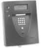
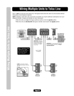
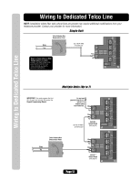
Wiring Multiple Units to Telco Line Wiring Multiple Units to Telco Line Up to 7 units can share the same phone line. The bypass boards allow the units to be disconnected without interrupting normal telephone operation. NOTE: Installation where fiber optic phone lines are present may require additional modifications from your telephone provider. Contact your provider for more information. • When the units are in use, the bypass switches must be set to the operate position. • When the units are disconnected, the bypass switches must be set to the bypass position. Home Phone Bypass Board for Unit 1 OPERATE BYPASS Bypass Board for Unit 2 OPERATE BYPASS Last Bypass Board BYPASS 4 3 2 1 Ring Tip Ring Tip HOME SYSTEM TELCO 4 3 2 1 Ring Tip Ring Tip HOME SYSTEM TELCO Ring Tip TELCO Telco Entrance Box Demarcation Point Ring Ring Tip Tip Tip Tip Ring Ring IMPORTANT: The Bypass Boards (located inside the property) allow access to the phone in case any of the units fail. IMPORTANT: You must program the unit ID's for each unit wired in the series. See Keypad Programming Manual. Never run Telco wires and High Voltage wires in the same conduit. The high voltage wires may interfere with the Telco wires, possibly causing the system to malfunction. Use 18-24 AWG 2 twisted pair DO NOT overload the removable terminal block connectors. One wire per hole. RES 3 4 Ring Tip TELCO 1 2 Ring Tip Unit ID 1 Output Board (See page 6) RES 1 2 Ring Tip TELCO 3 4 Ring Tip Unit ID 2 Output Board (See page 6) Page 10
-
 1
1 -
2
-
3
-
4
-
5
-
6
-
 7
7 -
 8
8 -
 9
9 -
 10
10 -
 11
11 -
 12
12 -
 13
13 -
 14
14 -
 15
15 -
 16
16 -
 17
17 -
18
-
19
-
20
-
21
-
22
-
23
-
24
-
25
-
26
-
27
-
28
-
29
-
30
-
31
-
32
 |
 |