LiftMaster GH GH Logic 4 Quick Start Guide Manual - Page 1
LiftMaster GH Manual
 |
View all LiftMaster GH manuals
Add to My Manuals
Save this manual to your list of manuals |
Page 1 highlights
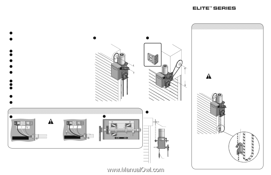
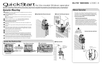
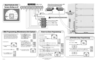
QuickStart for the model GH door operator IMPORTANT: This QuickStart is intended to highlight a typical installation. These instructions are not intended to be comprehensive. Since each application is unique, it is the responsibility of the purchaser, designer, installer and end user to ensure that the total door system is safe for its intended use. Please consult the manual and/or a qualified technician for further information. Operator Mounting 1a Wall Mount: The operator should generally be installed below the door shaft, and as close to the door as possible. 1b Bracket Shelf Mounting: The operator may be mounted either above or below the door shaft. NOTE: The optimum distance between the door shaft and operator drive shaft is between 12 - 15 inches. 2 Place door sprocket on the door shaft. Do not insert the key at this time. 3 Place drive sprocket on the appropriate side of the operator. Do not insert the key at this time. 4 Wrap chain drive around door sprocket and join roller chain ends together with master link. 5 Raise operator to approximate mounting position and position chain over operator sprocket. 6 Raise or lower operator until the chain is taut (not tight). Make sure the operator output shaft is parallel to door shaft and sprockets are aligned. When in position, secure the operator to wall or mounting bracket. 7 Align sprockets, insert key into keyway, and secure. 8 Place hand chain around hand chain wheel. 9 Run the power wires through the power wiring conduit hole in the electrical box enclosure. Connect the power to the operator. Connect the earth ground to the ground screw in the electrical box enclosure. Follow ALL local electrical codes. 10 Adjust the limit switches to open and close door properly. Make sure the limit nuts are positioned between the limit switches before proceeding with adjustments. 11 Radio programming and troubleshooting instructions inside cover of operator. 1a Right Hand Wall Mounted Operator 1b Bracket Shelf Mounted Operator OPTIONAL Mounting Bracket P/N 08-9098 Optimum Distance 12" - 15" Optimum Distance 12" - 15" LOGIC 4 Manual Operation This operator has provisions for manually operating the door in case of emergency or power failure. These operators are equipped with a manual hoist. An electrical interlock will disable the electrical controls when the hoist is used. Turn off power to the operator BEFORE manually operating your door. Electrical Interlock with Hoist To operate the hoist, pull the disconnect chain (small chain) to engage the hoist mechanism. The disconnect chain may be locked in position by slipping the end through the keyhole of the chain keeper mounted on the wall. Operate the door in the desired direction by pulling on one side or the other of the continuous loop hoist chain (large chain). The disconnect chain must be released from the chain keeper before the door will operate again electrically. Turn off power to the operator BEFORE manually operating your door. Electrical Interlock with Hoist Inside the Electrical Box 9 Single Phase Connections HOT NEUTRAL EARTH Three Phase Connections L1 L2 POWER WIRING USE COPPER WIRE ONLY 14 AWG Minimum Follow ALL national and local electrical codes. Power wiring ONLY! L1 L2 L3 DEDICATED CIRCUIT POWER WIRING USE COPPER WIRE ONLY DEDICATED CIRCUIT 10 Limit Switches Retaining CLOSE Plate Limit Nuts OPEN SAFETY Push Direction Limit Nut Will Move During Travel 7 Align Sprockets Be sure door sprocket is properly aligned with drive before securing to the shaft. Mount Chain Keeper 4' above floor Chain Keeper (with pad locking provisions) Chain Keeper (4' above floor)
-
 1
1 -
 2
2
 |
 |