LiftMaster H J-Quick Start Guide for L3 Manual - Page 1
LiftMaster H Manual
 |
View all LiftMaster H manuals
Add to My Manuals
Save this manual to your list of manuals |
Page 1 highlights
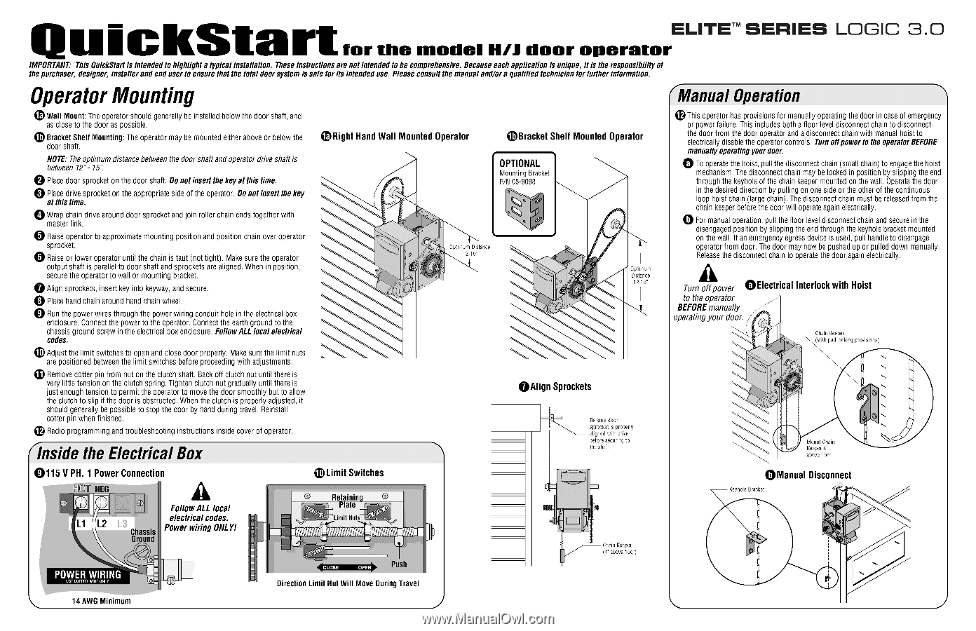
i ckStart SERIES LOGIC 3.0 for the Riedel H/J door operatorELITETm IMPORTANT: This QuickStart is intended to highlight a typical installation. These instructions are not intended to be comprehensive. Because each application is unique, it is the responsibility of the purchaser, designer, installer and end user to ensure that the total door system is safe for its intended use. Please consult the manual and/or a qualified technician for further information. Operator Mounting Wall Mount: The operator should generally be installed below the door shaft, and as close to the door as possible. Bracket Shelf Mounting: The operator may be mounted either above or below the door shaft. NOTE: The optimum distance between the door shaft and operator drive shaft is between 12"- 15". 0 Place door sprocket on the door shaft. Do not insert the key at this time. Place drive sprocket on the appropriate side of the operator. Do not insert the key at this time. 0 Wrap chain drive around door sprocket and join roller chain ends together with master link. 0 Raise operator to approximate mounting position and position chain over operator sprocket. Raise or lower operator until the chain is taut (not tight). Make sure the operator output shaft is parallel to door shaft and sprockets are aligned. When in position, secure the operator to wall or mounting bracket. 0 Align sprockets, insert key into keyway, and secure. 0 Place hand chain around hand chain wheel. 0 Run the power wires through the power wiring conduit hole in the electrical box enclosure. Connect the power to the operator. Connect the earth ground to the chassis ground screw in the electrical box enclosure. Follow ALL local electrical codes. D Adjust the limit switches to open and close door properly. Make sure the limit nuts are positioned between the limit switches before proceeding with adjustments. Remove cotter pin from nut on the clutch shaft. Back off clutch nut until there is very little tension on the clutch spring. Tighten clutch nut gradually until there is just enough tension to permit the operator to move the door smoothly but to allow the clutch to slip if the door is obstructed. When the clutch is properly adjusted, it should generally be possible to stop the door by hand during travel. Reinstall cotter pin when finished. e Radio programming and troubleshooting instructions inside cover of operator. inside the Electrical Box Right Hand Wall Mounted Operator 0Bracket Shelf Mounted Operator OPTIONAL Mounting Bracket P/N 08-9098 00 • Optimum Distance 0 12-15" C Optimum Distance 12-15" OAlign Sprockets Manual Operation e This operator has provisions for manually operating the door in case of emergency or power failure. This includes both a floor level disconnect chain to disconnect the door from the door operator and a disconnect chain with manual hoist to electrically disable the operator controls. Turn offpower to the operator BEFORE manually operating your door. 0 To operate the hoist, pull the disconnect chain (small chain) to engage the hoist mechanism. The disconnect chain may be locked in position by slipping the end through the keyhole of the chain keeper mounted on the wall. Operate the door in the desired direction by pulling on one side or the other of the continuous loop hoist chain (large chain). The disconnect chain must be released from the chain keeper before the door will operate again electrically. 0 For manual operation, pull the floor level disconnect chain and secure in the disengaged position by slipping the end through the keyhole bracket mounted on the wall. If an emergency egress device is used, pull handle to disengage operator from door. The door may now be pushed up or pulled down manually. Release the disconnect chain to operate the door again electrically. Turn off power °Electrical Interlock with Hoist to the operator BEFORE manually operating your door. Chain Keeper • (with pad locking provisions) 0 Be sure door sprocket is properly aligned with drive before securing to the shaft. Mount Chain Keeper 4' above floor 0115 V PH. 1 Power Connection NEG L1 L2 Chassis Ground Follow ALL local electrical codes. Power wiring ONLY! • I • • Limit Switches © Retainin © ate ° Qos4.0 ovo ° Limit Nuts osts CLOSE OPEN Push Direction Limit Nut Will Move During Travel Chain Keeper (4" above floor) °Manual Disconnect Keyhole Bracket 14 AWG Minimum
-
 1
1 -
 2
2
 |
 |