LiftMaster LMSC1000 Installation Manual - English French Spanish - Page 2
Installation, Reader Mounting
 |
View all LiftMaster LMSC1000 manuals
Add to My Manuals
Save this manual to your list of manuals |
Page 2 highlights
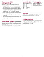
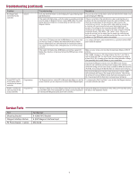
Installation Site layout plays a large role in where you can mount the reader and may prompt you to use a particular location/orientation. It is very important to be mindful of how reader placement affects where and how you mount the RFID tags/transponders on the vehicle. Here are some examples of reader placement and how they affect tag placement. Orientation Note: Minimize the distance between reader and tag as much as possible (shown as red line). Vertically Mounted Reader RF Signal Pattern Coverage Area Transponder ID Signal from Vehicle to System For best results use a signal checker to test desired installation position. After reader orientation has been selected make sure that all readers to be used at the site are installed in the same orientation to ensure consistent tag reads (all on the left/driver's side, for example). The example shown is a general recommendation, final location should be decided after field testing. Reader Reader Reader Tag Read Zone Tag not read Tag Read Zone Tag not read Tag Read Zone Preferred Tag Locations Preferred Tag Locations Preferred Tag Locations Correct Driver Side Reader Placement Correct Overhead Reader Placement NOTE: Use LMHNTG for rear view mirror tag location and LMUNTG for all other tag locations. The LMSC1000 generates and emits Radio Frequency (RF) energy which may cause interference with access control receivers. Avoid aligning the LMSC1000 read field within close proximity of any other receiving device antenna. Correct Passenger Side Reader Placement Reader Mounting Step 1: Install mounting bracket to the desired mounting location. Attach the round side of the bracket with appropriate screws. Adjustment Screws Step 2: Secure the reader to the mounting bracket by removing the mounting nuts from the mounting bolts located on the back of the reader. Place the reader bolts through the mounting bracket's supplied holes. Reinstall the mounting nuts/lock washers and re-tighten. Reader back Step 3: Once the reader is mounted, the reader's vertical orientation to the roadway can be adjusted using the adjustment screws. The specific angle is determined by the average pitch of the vehicle's tag mounting surface (e.g., windshield, headlamp, etc.). Mounting Bolts Ground Lug Optional U-Bolt Mounting Minimum Post Diameter 4" (10 cm) 3"-6" (7.6 - 15.2 cm) Backfill 3 ft. (0.9 m) Minimum Recommended Reader Height Front View Weatherproof Enclosure for power outlet and S2W Wiegand Interface (Not Supplied) 6 - 8 ft. (1.8 - 2.4 m) Set Post In Concrete The S2W Wiegand Interface Module and plug-in transformer shall be mounted in either the CAPXL enclosure or a Gate Operator Listed to UL 325, or a weather proof enclosure: UL Listed NITW or CYIV, Types 3X, 3RX, 3SX, 4X OR 6P. NOTE: Examples shown are general recommendations, final location should be decided upon field testing. Recommended Distance from Gate Top View Gate 1 ft. (0.3 m) Reader 3 - 4 ft. (0.9 - 1.2 m) 6 - 8 ft. (1.8 - 2.4 m) Arming Loop 2
-
 1
1 -
 2
2 -
 3
3 -
 4
4 -
 5
5 -
 6
6 -
 7
7 -
 8
8 -
9
-
10
-
11
-
12
-
13
-
14
-
15
-
16
-
17
-
18
-
19
-
20
-
21
-
22
-
23
-
24
 |
 |
