LiftMaster PPLX Installation Guide - Page 2
Installation, Wiring
 |
View all LiftMaster PPLX manuals
Add to My Manuals
Save this manual to your list of manuals |
Page 2 highlights
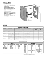
INSTALLATION 1 Position the mounting plate to the mounting surface and attach with the #6 mounting screws. 2 Drill a 3/4" hole for the cable (refer to illustration for location of the cable hole) and feed the cable through the hole as shown. 3 Plug the wire harness into the connector on the back of the reader. 4 Attach the reader to the mounting plate by inserting the top tabs into the slots on the top of the mounting plate. 5 Secure by installing either the 4x40 screw or the security screw into the hole on the bottom of the reader. Tabs go" Connector (on back of reader) WIRING PRODUCT MODEL/TYPE Maglock Commercial Door Operators Commercial Gate Operators Residential Gate Operators MG1300 Logic 4.0 Medium Duty Logic LiftMaster® Commercial Elite® Commercial Mega Operators Miracle-OneTM LA400 LA412/RSW/RSL LIFTMASTER® CONNECTIONS WHITE/BLACK (RELAY) WHITE/BROWN (RELAY) POWER SUPPLY FOR READER BLACK RED MG1300 Lock (Red + White) MG1300 Transformer (Black + White) - + Terminal 7 (Open) Terminal 4 (Common) - + Terminal 7 (Open) Terminal 3 (Common) - + Terminal 6 (Open) Terminal 5 (Common) - + Terminal 10 Terminal 9 - + Terminal 3 (Open Gate) Terminal 10 (Common) - + Terminal 21 (Strike Input N/O) Terminal 10 (Strike Input Common) - + SINGLE BUTTON COM - + SINGLE BUTTON CTRL PWR - + BASIC WIRE COLOR RED BLACK REMOTE OPEN STANDALONE 5-14 Vdc + GROUND - WHITE/BLACK WHITE/BROWN Latch Relay Latch Relay WIRING CONNECTIONS ADVANCED LED CONTROL WIEGAND 5-14 Vdc + GROUND N/A N/A WIRE COLOR GREEN WHITE VIOLET GRAY REMOTE OPEN STANDALONE DATA-0 DATA-1 N/A N/A ORANGE BROWN N/A REX LATCH + TIMER (2,1) YELLOW N/A BLUE N/A LED CONTROL WIEGAND DATA-0 DATA-1 N/A N/A GREEN LED INPUT (3, 1) RED LED INPUT (3, 1) BEEPER INPUT (1) HOLD (1) Connect to GROUND to activate (1), Input programmed for Remote Open (2), Input programmed for LED/Beeper Control (3) 2
-
 1
1 -
 2
2 -
 3
3 -
 4
4 -
 5
5 -
 6
6 -
 7
7 -
 8
8
 |
 |
