LiftMaster PPLX Installation Guide - Page 6
Advanced, Programming
 |
View all LiftMaster PPLX manuals
Add to My Manuals
Save this manual to your list of manuals |
Page 6 highlights
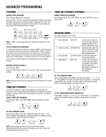
ADVANCED PROGRAMMING CONFIGURE RELAY OUTPUT (N/0 OR N/C) The reader relay is set at the factory to be normally open and to close upon presentation of a valid Card or upon activation of the remote open (Request to Exit) input, but it may be changed to normally closed operation. To configure the relay, enter Program Mode. Press the "Star" (*) Key TWICE. Then press either the "6" or "7". Press ENTER. OPTIONS 6 -Normally Open (Factory default) 7 -Normally Closed For example, to configure the relay normally closed, the following sequence would be entered: (STAR) (STAR) FJ (ENTER) USING THE READER AS A WIEGAND OUTPUT READER - The reader can be connected to a multi-door access control system using the Wiegand output. When any 34 bit PassportTM, 26 bit industry standard or 30 bit Sentex® credential device is presented to the reader, whether or not it has been programmed to the reader, the appropriate Credential Device ID will be sent out via the white and green wires. PROGRAMMING THE INPUTS The reader input is set at the factory as the Remote Open input. Connecting the brown and black/ground wire (usually through a normally-open push button switch or the contacts from an Exit input) will activate the relay for as long as the button is held, plus the time set for the latch timer. This input may also be configured as an LED Control, in which case grounding the brown wire will turn on the red LED, and grounding the orange wire will turn on the green LED. Additionally, grounding the yellow wire will turn on the beeper, and grounding the blue wire will activate the card data Hold function. SET THE RELAY LATCH TIMER (STRIKES AND MAGLOCKS) Enter Program mode. Press SET TIMER, and then press the digits representing the desired Latch Time (0 - 65535 seconds). Press ENTER. A Green LED and beep indicates Latch Timer setting update. NOTE: Setting Latch Timer for "0" seconds, actually results in a 0.25 second latch time. For example, to set the latch timer to 15 seconds, the following sequence would be entered: (SET TIMER) (15 Seconds) FJ (ENTER) To configure the input, enter Program Mode. Press the "Star" (*) Key TWICE. Then press either the "1" or "2" button. Press ENTER. Selections are: 1 - Remote Open (Factory Default - Standalone operation) 2 - LED Control (Standard Wiegand Reader Interface) For example, to program the input for LED control, the following sequence would be used: FJ (STAR) (STAR) (Input No. 2) (ENTER) For longer latch times it may be easier to set the timer with hour/minute notation. Press SET TIMER; then press the digits representing the number of hours (2 digits); then press the digits representing the number of minutes; then press the "Star" (*) Key; then press ENTER. (The maximum relay time is 18 hours and 00 minutes.) For example, to set the latch timer for 2 hours and 45 minutes the following sequence would be entered: (SET TIMER) 2 (2 Hours, 45 Minutes) (STAR) FJ (ENTER) If you have set an extended latch time, but need to interrupt it, use the following procedure: Enter Program Mode. Then press SET TIMER, then "1", and then Enter. After the Program Mode "times out" (15 sec), present a valid card to the reader. +Li+ .441-( 1 (SET TIMER) (Mode Number 1) (ENTER) After one second, the relay will return to its normal state. NOTE: You will then have to reprogram the latch timer to the desired time. The latch timer controls the reader relay. The Default latch time is 1 second, but it can be set to any value from 0.25 seconds to 18 hours. If it is set to 0 seconds, this pulses the reader relay for 0.25 second, sufficient for most gate and door operators. The beeper and LED are always fixed at one second. 6
-
 1
1 -
 2
2 -
 3
3 -
 4
4 -
 5
5 -
 6
6 -
 7
7 -
 8
8
 |
 |
