LiftMaster RSL12VDC RSL12VDC Installation Manual
LiftMaster RSL12VDC Manual
 |
View all LiftMaster RSL12VDC manuals
Add to My Manuals
Save this manual to your list of manuals |
LiftMaster RSL12VDC manual content summary:
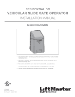
- LiftMaster RSL12VDC | RSL12VDC Installation Manual - Page 1
- LiftMaster RSL12VDC | RSL12VDC Installation Manual - Page 2
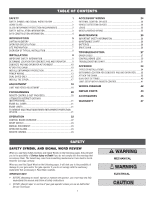
26 BATTERIES 26 DRIVE CHAIN 26 TROUBLESHOOTING 27 ERROR CODES 27 CONTROL BOARD LEDS 30 TROUBLESHOOTING CHART 31 APPENDIX 34 TYPES OF INSTALLATIONS 34 DETERMINE LOCATION FOR CONCRETE PAD AND OPERATOR.........35 ATTACH THE CHAIN 35 DUAL GATE SETTINGS 40 LIMIT SETUP WITH A REMOTE - LiftMaster RSL12VDC | RSL12VDC Installation Manual - Page 3
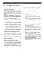
SLIDE AND SWING GATE OPERATOR GATE device to cover both the opening and closing directions is in accordance INSTRUCTIONS. • NEVER let children operate or play with gate gate is NOT moving. • KEEP GATES PROPERLY MAINTAINED. Read the owner's manual. Have a qualified service person make repairs to gate - LiftMaster RSL12VDC | RSL12VDC Installation Manual - Page 4
• Photoelectric Sensors • Screen Mesh • Vertical Posts • Instructional and Precautionary Signage 4. Install the gate operator only when: a. The operator is appropriate for the construction and the usage class of the gate. b. All openings of a horizontal slide gate are guarded or screened from the - LiftMaster RSL12VDC | RSL12VDC Installation Manual - Page 5
slide gates: 3.1.1 All weight bearing exposed rollers 8 feet (2.44 m), or less, above grade shall be guarded or covered. 3.1.2 All openings nearest the roadway, (such as a gate support post) and the gate frame when the gate is in either the fully open position or the fully closed position, shall - LiftMaster RSL12VDC | RSL12VDC Installation Manual - Page 6
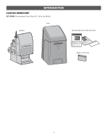
INTRODUCTION CARTON INVENTORY NOT SHOWN: Documentation Packet, Chain #41 - 30 feet, Eye Bolt Kit Cover Operator Warning Signs (2) and Warranty Card Battery 12 Vdc 7AH 5 - LiftMaster RSL12VDC | RSL12VDC Installation Manual - Page 7
SPECIFICATIONS This model is intended for use in vehicular slide gate applications: Usage Classification Main AC Supply System Operating Voltage Accessory Power Solar Power Max Maximum Gate Weight Maximum Gate Travel Distance Maximum Gate Travel Speed Maximum Daily Cycle Rate Maximum Duty Cycle - LiftMaster RSL12VDC | RSL12VDC Installation Manual - Page 8
SITE PREPARATION Check the national and local building codes BEFORE installation. CONDUIT & CONCRETE PAD Conduit must refer to specifications). VEHICLE LOOPS The vehicle loops allow the gate to stay open when vehicles are obstructing the gate path. Suggested for vehicles 14 feet (4.27 m) or - LiftMaster RSL12VDC | RSL12VDC Installation Manual - Page 9
Identify your installation type (refer to the Appendix in the back of the manual for more information). NOTE: One or more non-contact sensors shall be located where the risk of entrapment or obstruction exists at either the opening or closing direction. Care shall be exercised to reduce the risk of - LiftMaster RSL12VDC | RSL12VDC Installation Manual - Page 10
and trailing edges, and post mounted both inside and outside a horizontal swing gate. Non-contact sensors such as photoelectric sensors MUST be mounted across the gate opening and operate during BOTH the open and close cycles. • Entrapment protection devices MUST be installed to protect anyone - LiftMaster RSL12VDC | RSL12VDC Installation Manual - Page 11
" 6" Above Ground Below the frost line. Check all national and local codes. 24" (61 cm) STEP 3 ATTACH THE CHAIN Refer to the Appendix for rear installation step 3, page 35. DO NOT run the operator until instructed. 1. Manually open the gate and line up the front bracket so the chain will be level - LiftMaster RSL12VDC | RSL12VDC Installation Manual - Page 12
MUST be installed to protect anyone who may come near a moving gate. • Locate entrapment protection devices to protect in BOTH the open and close gate cycles. • Locate entrapment protection devices to protect between moving gate and RIGID objects, such as posts or walls. STEP 4 INSTALL ENTRAPMENT - LiftMaster RSL12VDC | RSL12VDC Installation Manual - Page 13
the wiring diagram or the specific entrapment protection device manual for more information. These entrapment protection device inputs gate closing the gate will open to the full open position and resets the Timer-to-Close. This input will be disregarded during gate opening codes for proper depth 12 - LiftMaster RSL12VDC | RSL12VDC Installation Manual - Page 14
that time the unit may be returned to service. • Disconnect power at the fuse box BEFORE in accordance with national and local electrical codes. NOTE: The operator should be on Follow the directions according to your application. For dual gate applications, power will have to be connected to each - LiftMaster RSL12VDC | RSL12VDC Installation Manual - Page 15
in the transformer. J15 Plug Red (+) (solar wires) Black (-) 7AH Battery To use a 33AH battery in place of the 7AH battery, follow the instructions below. The 33AH application requires the 33AH wire harness (Model K94-37236). 33AH BATTERY 1. Unplug the transformer. 2. Unplug the J15 plug labeled - LiftMaster RSL12VDC | RSL12VDC Installation Manual - Page 16
Wired dual gate applications will have a longer battery standby time than wireless applications. WIRELESS DUAL GATES TO ACTIVATE THE primary operator. The yellow NETWORK LED will light. 4. Press and release the OPEN test button to assign this operator as network primary. 5. Press and release the - LiftMaster RSL12VDC | RSL12VDC Installation Manual - Page 17
close before the other. The operator with the LOCK/BIPART DELAY switch ON will delay from the close limit when opening and be the first to close from the open limit. SLIDE GATE APPLICATIONS: Not applicable, set to OFF. AC & BATT FAIL BACKDRIVE • SYNCHRONIZED CLOSE The BIPART DELAY is also used in - LiftMaster RSL12VDC | RSL12VDC Installation Manual - Page 18
INSTALLATION STEP 8 INSTALL THE COVER 1. Slide the cover over the operator. 2. Align the hole in the cover with the threaded hole in the operator's chassis and secure the cover with the provided 5/16-18 screw. The basic installation is complete. 5/16-18 Screw 17 - LiftMaster RSL12VDC | RSL12VDC Installation Manual - Page 19
which limit is being set. 4. Press and hold one of the MOVE GATE button to move the gate to the other limit. 5. Press and release the SET CLOSE or SET OPEN button depending on which limit is being set. 6. Cycle the gate open and close. This automatically sets the force. 2 AC & BATT FAIL BACKDRIVE - LiftMaster RSL12VDC | RSL12VDC Installation Manual - Page 20
injury to a person. The force setting is the same for both the open and close gate directions. 1. Open and close the gate with the TEST BUTTONS. 2. If the gate stops or reverses before reaching the fully open or closed position, increase the force by turning the force control slightly clockwise - LiftMaster RSL12VDC | RSL12VDC Installation Manual - Page 21
open only. The Timer-to-Close can be set to close the gate. 1. Press and release the LEARN button (operator will beep and green XMITTER LED will light). 2. Press the OPEN if not installed and used in accordance with the instructions, may cause harmful interference to radio communications. However, - LiftMaster RSL12VDC | RSL12VDC Installation Manual - Page 22
beep if programming is successful. The status as shown by the LiftMaster Internet Gateway app will be either "open" or "closed". The gate operator can then be controlled through the LiftMaster Internet Gateway app. ERASE ALL CODES 1. Press and release the LEARN button (operator will beep and green - LiftMaster RSL12VDC | RSL12VDC Installation Manual - Page 23
version, and error codes. The operator type will display as "SL" followed by a "12" which indicates the operator type as RSL12VDC. The firmware version will show after the operator type, example "1.2". 12 BACKDRIVE Switch: Set to MANUAL will allow the gate to be manually pushed open or closed if - LiftMaster RSL12VDC | RSL12VDC Installation Manual - Page 24
and will energize the solenoid lock for two minutes and disable the maglock for two minutes. MANUAL DISCONNECT Press the reset switch to RESET/DISCONNECT to allow the gate to be opened and closed manually. To resume normal operation press the reset switch to NORMAL OPERATION. OPERATOR ALARM If - LiftMaster RSL12VDC | RSL12VDC Installation Manual - Page 25
for photoelectric sensor vehicle detection for the close direction. When an obstruction is sensed during gate closing the gate will open to the full open position. This input will be disregarded during gate opening and resets the Timer-to-Close. CLOSE EDGE (2 Terminals) The CLOSE EDGE input is for - LiftMaster RSL12VDC | RSL12VDC Installation Manual - Page 26
safeties and resets alarm condition). If maintained, pauses Timer-to-Close at OPEN limit. Opens a closing gate and holds open an open gate (within line-of-sight). • CLOSE and COM: Closes an open gate. Hard close (maintained switch overrides external safeties and resets alarm condition within - LiftMaster RSL12VDC | RSL12VDC Installation Manual - Page 27
AND FOLLOW ALL INSTRUCTIONS. • ANY manual disconnect release ONLY when the gate is NOT moving. • KEEP GATES PROPERLY MAINTAINED. Read the owner's manual. Have a qualified service person make repairs to gate hardware. • ALL maintenance MUST be performed by a LiftMaster professional. • Activate gate - LiftMaster RSL12VDC | RSL12VDC Installation Manual - Page 28
TROUBLESHOOTING To protect against fire and electrocution: • DISCONNECT power (AC or solar and battery) BEFORE installing or servicing operator. For continued protection against fire: • Replace ONLY with fuse of same type and rating. ERROR CODES NOTE: When cycling or disconnecting power (ac/dc) - LiftMaster RSL12VDC | RSL12VDC Installation Manual - Page 29
- LiftMaster Plug-in Loop Detector only) Check loop wiring throughout connection. May be a short in the loop, or an open connection in the loop. Wireless edge battery low Replace batteries in wireless edge. Battery shorted Check battery harness for short to chassis Run-Distance Error Gate - LiftMaster RSL12VDC | RSL12VDC Installation Manual - Page 30
TROUBLESHOOTING ERROR CODES continued... Some errors are saved in the error code history and some are not. If an error is not saved it will briefly appear on the error code display as it occurs, then disappear. Error Code 66 67 68 69 70 71 72 73 74 75 80 81 82 83 91 93 99 Meaning OPEN EYE/EDGE - LiftMaster RSL12VDC | RSL12VDC Installation Manual - Page 31
TROUBLESHOOTING CONTROL BOARD LEDS STATUS LEDS INPUT OFF POWER gate is stopped The gate is opening or closing MEDIUM BLINK (1 blink per second) FASTEST BLINK (8 blinks per second) Operator is in E1 (single entrapment) The operator is in E2 (double entrapment) BATT LOW OFF ON No battery error - LiftMaster RSL12VDC | RSL12VDC Installation Manual - Page 32
TROUBLESHOOTING TROUBLESHOOTING CHART SYMPTOM POSSIBLE CAUSES SOLUTIONS Operator does not a) No power to control board a) Check AC and battery power run and error code b) Open fuse b) Check fuses display not on. c) If on battery power only, low or dead batteries c) Charge batteries by AC - LiftMaster RSL12VDC | RSL12VDC Installation Manual - Page 33
TROUBLESHOOTING TROUBLESHOOTING CHART continued... SYMPTOM POSSIBLE CAUSES Obstruction in a) Force adjustment needed gate's path does not cause gate to stop and reverse Photoelectric sensor does not stop or reverse gate batteries On dual-gate system, incorrect gate opens first or closes - LiftMaster RSL12VDC | RSL12VDC Installation Manual - Page 34
TROUBLESHOOTING TROUBLESHOOTING CHART continued... SYMPTOM Solenoid lock not working correctly. POSSIBLE CAUSES board a) Add more solar panels b) Reduce the accessory power draw by using LiftMaster low power accessories c) Replace batteries d) Relocate the solar panels away from obstructions - LiftMaster RSL12VDC | RSL12VDC Installation Manual - Page 35
TYPES OF INSTALLATIONS STANDARD INSTALLATION The illustration is an example of a standard installation. APPENDIX Gate Rail Stop (Inside Property) ! Gate Rail Stop REAR INSTALLATION The illustration is an example of a rear installation. Gate Rail Stop (Inside Property) ! Gate Rail Stop 34 - LiftMaster RSL12VDC | RSL12VDC Installation Manual - Page 36
of the gate (in the OPEN position). The space between the gate and the output sprocket must be a minimum of 4 inches. 2. Lay out the concrete pad. REAR INSTALLATION 4" (10 cm) 24" (61 cm) 24" (61 cm) STEP 3 ATTACH THE CHAIN REAR INSTALLATION ONLY DO NOT run the operator until instructed. NOTE - LiftMaster RSL12VDC | RSL12VDC Installation Manual - Page 37
performance. We recommend LiftMaster low power draw accessories open area clear of obstructions and shading for the entire day. The gate operator is not supported GUIDE The RSL12VDC has best in class solar performance due to highly efficient electronics that draw very little power while the gate - LiftMaster RSL12VDC | RSL12VDC Installation Manual - Page 38
STEP 6 continued... SOLAR PANEL(S) SOLAR USAGE GUIDE APPENDIX SOLAR ZONES 3 NOT AVAILABLE 2 3 1 2 1 NOT AVAILABLE 1 SOLAR GATE CYCLES PER DAY BATTERY CURRENT DRAW (mA) 5W SOLAR PANEL 6 25 30 40 60 10W SOLAR PANEL 6 25 30 50 100 20W SOLAR PANEL 6 25 - LiftMaster RSL12VDC | RSL12VDC Installation Manual - Page 39
APPENDIX STEP 6 continued... SOLAR PANEL(S) The location of the panel(s) is critical to the success of the installation. In general, the panel(s) should be mounted using the provided angle bracket facing due south. Use a compass to determine direction. The solar panel(s) should be mounted in an - LiftMaster RSL12VDC | RSL12VDC Installation Manual - Page 40
two bolts into the track located on the back of the solar panel(s). 3. Slide bolts in track away from bolt hole and align both bolts. 4. Secure in parallel to achieve the desired wattage (30W maximum). Proceed to the Dual Gate section (if applicable) or proceed to the Adjustment section. J15 Plug ( - LiftMaster RSL12VDC | RSL12VDC Installation Manual - Page 41
Bi-Part Delay: OFF (will open first and close last) Tandem Mode: OFF Synchronized Close: ON ACCESSORY PRIMARY OPERATOR Remote Controls Program remote controls 1 to 50 to the primary operator. LiftMaster Program to primary Internet Gateway operator. Garage and Gate Program to primary Monitor - LiftMaster RSL12VDC | RSL12VDC Installation Manual - Page 42
button on the remote control. 7. Press and release the CLOSE button on the remote control again to set the close limit. 8. Cycle the gate open and close. This automatically sets the force. When limits are set properly the operator will automatically exit limit setting mode. ADJUST THE LIMITS If - LiftMaster RSL12VDC | RSL12VDC Installation Manual - Page 43
BEFORE installing or servicing operator. For continued or OFF nks ult) Open Loop Shorted Loop Failed Authentication Cable Primary/Secondary link to other gate operator Ground the shield of the Loop Wire Loop Wire Loop Field Wiring Field Wiring OPEN CLOSE 1 EYE ONLY 2 EYE/ EDGE 3 - LiftMaster RSL12VDC | RSL12VDC Installation Manual - Page 44
REPAIR PARTS ITEM 1 2 3 4 5 PART NUMBER K73-37060 K13-37061 K76-34697-3 K16-GT2-9 K17-37318 6 K15-41B16GKEH 7 K32-34701-5 8 K76-37251 9 K1D8059-1CC 10 K76-37016 11 K77-36541 12 K76-37253 13 K77-37319 14 K180A0357 15 K76-37298 16 K13-34729 17 Q013 INDIVIDUAL PARTS - LiftMaster RSL12VDC | RSL12VDC Installation Manual - Page 45
4 5 12 7 6 17 1 2 REPAIR PARTS 3 15 14 11 9 13 10 8 16 44 - LiftMaster RSL12VDC | RSL12VDC Installation Manual - Page 46
mounted and wired separately inside control box. LiftMaster low power accessory. Model LD7LP VEHICLE SENSING detect a car as it approaches and will then open the gate. Model CP3 3-BUTTON REMOTE CONTROL The 3-button remote to operate gate operator from outside by entering a 4-digit code on a - LiftMaster RSL12VDC | RSL12VDC Installation Manual - Page 47
MISCELLANEOUS LIFTMASTER® INTERNET GATEWAY Internet enabled accessory which connects to the computer and allows you to monitor and control gate operators and lighting accessories enabled by MyQ® technology. Model 828LM BATTERIES Gate access system batteries replace or upgrade the gate operator - LiftMaster RSL12VDC | RSL12VDC Installation Manual - Page 48
this product. Then send this product, pre-paid and insured, to our service center for warranty repair. You will be advised of shipping instructions when you call. Please include a brief description of the problem and a dated proof-of purchase receipt with any product returned for warranty repair
-
 1
1 -
 2
2 -
 3
3 -
 4
4 -
 5
5 -
 6
6 -
 7
7 -
8
-
9
-
10
-
11
-
12
-
13
-
14
-
15
-
16
-
17
-
18
-
19
-
20
-
21
-
22
-
23
-
24
-
25
-
26
-
27
-
28
-
29
-
30
-
31
-
32
-
33
-
34
-
35
-
36
-
37
-
38
-
39
-
40
-
41
-
42
-
43
-
44
-
45
-
46
-
47
-
48
 |
 |
