LiftMaster SL3000UL3 Owners Manual
LiftMaster SL3000UL3 Manual
 |
View all LiftMaster SL3000UL3 manuals
Add to My Manuals
Save this manual to your list of manuals |
LiftMaster SL3000UL3 manual content summary:
- LiftMaster SL3000UL3 | Owners Manual - Page 1
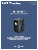
The Chamberlain Group, Inc. 845 Larch Avenue Elmhurst, Illinois 60126-1196 www.liftmaster.com SL3000UL™ VEHICULAR SLIDE GATE OPERATOR OWNER'S MANUAL THE SL3000UL™ IS FOR USE ON VEHICULAR PASSAGE GATES ONLY AND NOT INTENDED FOR USE ON PEDESTRIAN PASSAGE GATES. INTENDED FOR PROFESSIONAL INSTALLATION - LiftMaster SL3000UL3 | Owners Manual - Page 2
- LiftMaster SL3000UL3 | Owners Manual - Page 3
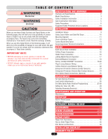
Programming 27-28 Setting the Timer (On, Off 29 Adjusting Reversing Sensor(s 30 MAINTENANCE AND OPERATION Maintenance 31 OPERATION Built-In Reset Switch 32 Audio Alarm 32 EMERGENCY MANUAL RELEASE 33 ACCESSORIES 34 WIRING DIAGRAMS 35-42 TROUBLESHOOTING 43-44 REPAIR PARTS Repair Part - LiftMaster SL3000UL3 | Owners Manual - Page 4
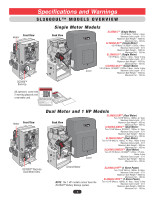
- 105 lbs. DC2000™ Back-Up All operators come with 2 warning placards and a warranty card. Heater Front View Dual Motor and 1 HP Models Back View Cover SL3000ULDM™ (Dual Motor) Two-1/2 HP Motors, 120Vac, 4.7 Amp. Maximum Gate Length - 37 ft. Maximum Gate Weight - 800 lbs. Maximum Pull - 100 - LiftMaster SL3000UL3 | Owners Manual - Page 5
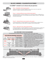
(five or more single family units) hotel, garage, retail store or other building servicing the general public. Class III - Industrial/limited access vehicular gate operator A vehicular gate operator (or system) intended for use in a industrial location or building such as a factory or loading dock - LiftMaster SL3000UL3 | Owners Manual - Page 6
shall not open into public access areas. 7. The gate must be properly installed and work freely in both directions prior to the installation of the gate operator. 8. Controls intended for user activation must be located at least six feet (6') away from any moving part of the gate and where the - LiftMaster SL3000UL3 | Owners Manual - Page 7
wire shall not be less than 6 feet (1.83 m) above grade. 1.5 An existing gate latch shall be disabled when a manually operated gate is retrofitted with a powered gate operator. 1.6 A gate (such as a gate support post) and the gate frame when the gate is in either the fully open position or the fully - LiftMaster SL3000UL3 | Owners Manual - Page 8
devices to protect in BOTH the open and close gate cycles. • Locate entrapment protection devices to protect between moving gate and RIGID objects, such as posts or walls. Property owners MUST never mount any gate operating device near the gate's path! Property owners MUST never allow anyone to - LiftMaster SL3000UL3 | Owners Manual - Page 9
SDEaCnInygsciedlreeLSoaofepty Inside Property 7 Gate Rail Stops For safety reasons, physical stops MUST be installed on both ends of the gate rail prior to installation of the gate operator. This will assure that the gate does not derail while opening or closing fully. - LiftMaster SL3000UL3 | Owners Manual - Page 10
allows the gate to stay open when vehicles are obstructing the gate path. Suggested for vehicles 14 feet or longer. See Loop Detector Wiring. Gate Rail Stops For safety reasons, physical stops MUST be installed on both ends of the gate rail prior to installation of the gate operator. This will - LiftMaster SL3000UL3 | Owners Manual - Page 11
on ends of gate rail. Master/Second Operators Maximum gate length 37 ft. for each gate. UL approved catch rollers with safety covers. Maximum gate weight varies for operators. Separate power supply for each operator. Warning Placard on both sides of each gate. 2 inch wire grid safety screen - LiftMaster SL3000UL3 | Owners Manual - Page 12
stop at least five inches from an obstructing wall. 5" End View of Gate and Wall NOTE: For safety reasons, physical stops MUST be installed on both ends of the gate rail prior to installation of the gate operator. This will assure that the gate does not derail while opening or closing fully. 10 - LiftMaster SL3000UL3 | Owners Manual - Page 13
Top Inside View MOUNTING OPERATOR 8.25" Conduit area without battery back-up. 13" 4 Concrete Anchors 1/2" x 3 1/2" High voltage conduit. Above Ground 3" heavy steel posts can be U-bolted to mounting plate and cemented in ground. Power and control wiring should be run in separate conduits. 11 - LiftMaster SL3000UL3 | Owners Manual - Page 14
in open position. Rear Operator Position Cut the chain slot 17 1/2" high on cover. Low idler pulley position. CHAIN DISTANCE AND HEIGHT ON GATE CORRECT INSTALLATION INCORRECT INSTALLATION Don't connect chain too tight to gate. Top View of Gate 2 inch wire grid safety screen is missing. Chain - LiftMaster SL3000UL3 | Owners Manual - Page 15
Sensor - Limited Adjustment, page 30. 8 Gate Opening Direction Selector - Open Left, Open Right. 19 Reverse Sensor - Gate hit obstruction when ON. See page 30. 9 Gate Locked LED - Maglock/Solenoid is activated when on. 20 System On LED - Operator is successfully performing a command. 10 Reset - LiftMaster SL3000UL3 | Owners Manual - Page 16
operation of external devices: • ENSURE bare wires make good contact inside removable terminal connections. • DO NOT let wire insulation interfere with connection. Remote that will Open and Close with a single push of a button. All other terminals will ONLY Open with a single push of a button. 14 - LiftMaster SL3000UL3 | Owners Manual - Page 17
. The earth ground rod must be located within 3 feet from the gate operator. Use the proper type earth ground rod for your local area. The ground wire must be a single, whole piece of wire. Never splice two wires for the ground wire. If you should cut the ground wire too short, break it, or destroy - LiftMaster SL3000UL3 | Owners Manual - Page 18
dedicated circuit for each operator. Input power 120Vac, 60 Hz. Earth Ground Rod Highly Recommended! See previous page. 120Vac Power Wire 1/2 HP and Dual FT 1100 FT HEATER POWER CONNECTION Connect the black, white and ground wire from the heater to the 120Vac power supply as shown. When the - LiftMaster SL3000UL3 | Owners Manual - Page 19
Dept Strike Open Loop Key Switch Push Button Radio Receiver NOTE: Disconnect the second radio receiver when using a master/second setup. Partial Master/Individual Control In order for the following operation to occur, follow the instructions. EXAMPLE: There is a double gate, the entry gate is to - LiftMaster SL3000UL3 | Owners Manual - Page 20
-BACKUP SYSTEM ON SENSORS 1 3 1 3 REVERSE SENSOR TIMER 60 3 OFF OPEN LEFT 1 3 ON OPEN RIGHT COMMAND PROCESSED FIRE DEPT. STRIKE OPEN RADIO RECEIVER GATE LOCKED EXIT LOOP SAFETY LOOP CENTER LOOP RESET MOTOR CLOSE STOP OPEN POWER OVERLOAD MADE IN USA CENTER SAFETY EXIT Relay - LiftMaster SL3000UL3 | Owners Manual - Page 21
"Reverse Sensor" setting. See Adjustment Reversing Sensor(s). Socket Reset button and interlock wires, Do Not Remove. 120Vac Power Failure Manual Mode Push and Hold to operate gate. Auto Mode Gate automatically opens. 120Vac Power On, OmniControl™ Board Malfunction Turn the 120Vac power - LiftMaster SL3000UL3 | Owners Manual - Page 22
interlock wires, Do Not Remove. Push and HOLD button to Open. Push button again and HOLD to Close. 1234567 Manual Key Switch See Accessories Turn and HOLD key to Open. Turn key again and HOLD to Close. Manual 3-Button N.O. 3 N.O. 2 N.O. 1 Com 4 4 Com Com 4 Push and HOLD a button to operate - LiftMaster SL3000UL3 | Owners Manual - Page 23
The wire MUST operator before installing plug-in loop detectors. Use a different frequency for every loop detector installed. Exit Loop Inside Safety Loop NOTE: Refer to the plug-in loop detector manual for more specific information. Plug-In "Safety" Loop Detector - Allows gate to stay open - LiftMaster SL3000UL3 | Owners Manual - Page 24
Fire Dept Strike Open Loop Key Switch Push Button Radio Receiver ProIpnesritdye See Accessories 120Vac "Safety" Loop Detector - Allows gate to stay open when vehicles from the end of the feeder slot to the loop detector. The wire is continuously wound in the loop saw cut for the required number - LiftMaster SL3000UL3 | Owners Manual - Page 25
BOTH the open and close gate cycles. • Locate entrapment protection devices to protect between moving gate and RIGID objects, such as posts or walls. NOTE: When touched, these electrically activated edge sensors immediately signal the gate operator to stop and reverse. Property owners are obligated - LiftMaster SL3000UL3 | Owners Manual - Page 26
owners are obligated to test photoelectric sensors monthly. Entrapment Danger Gate in Open gate: • Locate entrapment protection devices to protect in BOTH the open and close gate cycles. • Locate entrapment protection devices to protect between moving gate Strike Open Loop Key Switch Push Button - LiftMaster SL3000UL3 | Owners Manual - Page 27
CONNECTIONS NOTE: Refer to the Omni Option Board manual for more specific information. Purchased separately from Chamberlain Elite. See Accessories. QCC A B OPEN STOP CLOSE MAGLOCK ALARM ARMED M/S LINK W4 Quick Close Circuit Allows the gate's close cycle to close quicker than the OmniControl - LiftMaster SL3000UL3 | Owners Manual - Page 28
SENSORS 1 3 1 3 REVERSE SENSOR TIMER 60 3 OFF OPEN LEFT 1 3 ON OPEN RIGHT COMMAND PROCESSED FIRE DEPT. STRIKE OPEN RADIO RECEIVER GATE LOCKED EXIT LOOP SAFETY LOOP CENTER LOOP RESET MOTOR CLOSE STOP OPEN POWER OVERLOAD MADE IN USA RADIO Open to the RIGHT CENTER SAFETY EXIT - LiftMaster SL3000UL3 | Owners Manual - Page 29
. WARNING To prevent possible SERIOUS INJURY or DEATH from a moving gate or garage door: • ALWAYS keep remote controls out of reach of children. NEVER permit children to operate, or play with remote control transmitters. • Activate gate or door ONLY when it can be seen clearly, is properly adjusted - LiftMaster SL3000UL3 | Owners Manual - Page 30
. Learn Button Programming Radio Receiver: 1. Press and release the "Learn" button on the receiver. The learn indicator light will glow steadily for 30 seconds. 2. Within 30 seconds, press and hold the button on the hand-held remote. The operator will now operate when the push button on the remote - LiftMaster SL3000UL3 | Owners Manual - Page 31
, OFF) NSOR NSOR Single Operator To use the automatic close for the gate system the timer switch should be put in the "ON" position. To use the push close command, the timer should be switched to the "OFF" position. Push button once to open gate, push button again to close gate. Set Timer 1 to 60 - LiftMaster SL3000UL3 | Owners Manual - Page 32
RADIO RECEIVER GATE LOCKED EXIT LOOP SAFETY LOOP CENTER LOOP RESET MOTOR CLOSE STOP OPEN POWER OVERLOAD MADE IN USA CENTER SAFETY EXIT DC2000™ Reverse Sensor The DC2000™ has a separate reverse sensor that will need to be adjusted. The 120Vac CLASS I, II, III, IV operator power needs - LiftMaster SL3000UL3 | Owners Manual - Page 33
ANY maintenance. 9. ALL maintenance MUST be performed by a Chamberlain Elite professional. 10. SAVE THESE INSTRUCTIONS. MAINTENANCE: 1. Disconnect power before servicing. 2. The gate area should be kept clean to insure proper operation. 3. Check for belt tightness. 4. Check chain for tightness - LiftMaster SL3000UL3 | Owners Manual - Page 34
. If the audio alarm goes off, always check the gate area for: • Obstructions in the gate path. • Damage to the gate and/or gate operator. Pressing the reset switch will stop a moving gate during a normal open/close cycle, like a stop button. The operator does NOT need to be reset after doing this - LiftMaster SL3000UL3 | Owners Manual - Page 35
1 Main Dept. Manu. 2 Rm NOTE: Use the dedicated breaker switch to disconnect power to the operator. Turn the power OFF! Push the crank tool in hole. Safety releases will separate. Turn the crank to open the gate. Remove crank tool. NOTE: YOU may use a cordless power drill (6"/sec) for quicker - LiftMaster SL3000UL3 | Owners Manual - Page 36
V-Groove Power Wheels Series 6 inch Remote Controls Relay Adapter Module Part # Q400MAU Quick Close Circuit (QCC) Part # OQCCOMNI For more information about accessories: www.chamberlain.com 3-Button Control Station Part # 02-103 Omni Option Board Part # OOMNIEXB UL Approved Round Sensing Edge - LiftMaster SL3000UL3 | Owners Manual - Page 37
WIRING DIAGRAM • SL3000UL™ Electronic Power Strip Chassis Ground White Wires Black Wires OPEN LEFT 1 3 ON OPEN RIGHT COMMAND PROCESSED FIRE DEPT. STRIKE OPEN RADIO RECEIVER GATE LOCKED EXIT LOOP SAFETY LOOP CENTER LOOP RESET MOTOR CLOSE STOP OPEN Open Loop Key Switch Push Button - LiftMaster SL3000UL3 | Owners Manual - Page 38
WIRING TABLE • SL3000UL™ J # J Pin # J1 1 J1 2 J1 3 J1 4 J1 5 J1 6 J1 7 J1 8 J1 9 2 to 10Vdc Master/Second Link Input Radio Receiver, Strike Open Push Button, Fire Dept Key Switch Inputs External Loop Detector Center, Safety, Exit Wires Input NOTE: See diagram on previous page. - LiftMaster SL3000UL3 | Owners Manual - Page 39
WIRING DIAGRAM • SL3000ULDM™ Electronic Power Strip Chassis Ground White Wires Black Wires OPEN LEFT 1 3 ON OPEN RIGHT COMMAND PROCESSED FIRE DEPT. STRIKE OPEN RADIO RECEIVER GATE LOCKED EXIT LOOP SAFETY LOOP CENTER LOOP RESET MOTOR CLOSE STOP OPEN Open Loop Key Switch Push Button - LiftMaster SL3000UL3 | Owners Manual - Page 40
J3 1 J3 2 J3 3 J3 4 J3 5 J3 6 WIRING TABLE • SL3000ULDM™ Signal Type OmniControl™ Board Direction Level (+/- 10%) Input Connection Safety Open Push Button, Fire Dept Key Switch Inputs External Loop Detector Center, Safety, Exit Wires Input 38 NOTE: See diagram on previous page. - LiftMaster SL3000UL3 | Owners Manual - Page 41
OPEN RADIO RECEIVER GATE LOCKED EXIT LOOP SAFETY LOOP CENTER LOOP RESET MOTOR CLOSE STOP OPEN POWER OVERLOAD MADE IN USA Left Motor Relay Adapter Module (Optional) UL Alarm Limit Box Assy Right Factory Heater NOTE: Wires Dept Strike Open Loop Key Switch Push Button Radio Receiver Green - LiftMaster SL3000UL3 | Owners Manual - Page 42
Loop Detector (5) In Exit External Loop Detector (6) In - - 2 to 10Vdc 2 to 10Vdc 2 to 10Vdc 2 to 10Vdc Master/Second Link Input Radio Receiver, Strike Open Push Button, Fire Dept Key Switch Inputs External Loop Detector Center, Safety, Exit Wires Input 40 NOTE: See diagram on previous page. - LiftMaster SL3000UL3 | Owners Manual - Page 43
WIRING DIAGRAM • DC2000™ FOR SINGLE AND DM CENTER SAFETY EXIT NOTE: This diagram only shows the DC2000™ wiring and all other wiring not shown is the same as the diagram on the single or dual motor models. The 1 HP models Can Not have the DC2000™ Battery Backup system. Not Used W4 G B A MS LINK - LiftMaster SL3000UL3 | Owners Manual - Page 44
to it alone. Normal operation will be controlled by separate devices wired to the OmniControl™ board and surge suppressor. Radio Receiver 315 MHz 12Vdc to J6 Pin 3,4 OmniControl™ Board (Sensor) 1 2 3 4 5 6 7 J20 1 Open N.O. 2 Close N.O. 3 Stop N.O. Manual Three Button Dry Contact 6 + 12Vdc - LiftMaster SL3000UL3 | Owners Manual - Page 45
Cause: Radio receiver's signal is not getting to gate operator. Solution: Check wiring between receiver and surge suppressor. 4. Probable Cause: Remote is not programmed correctly. Resetting Motor(s) NOTE: Press firmly to reset thermal breaker button(s). A long slotted screwdriver may be needed to - LiftMaster SL3000UL3 | Owners Manual - Page 46
more and try again. 1. This is a normal response of the gate operator. It does not represent necessarily that there is a problem. 1. This is a normal response of the gate operator. It does not represent necessarily that there is a problem. Check inputs for command. 1. Any re-new command will resume - LiftMaster SL3000UL3 | Owners Manual - Page 47
Repair Parts REPAIR PART ILLUSTRATIONS SL DM SL CLASS I, II, III, IV *Q029 Q033 K75-51048 ODC2000SL Q024 DM / 1 HP 312HM Q030 K75-50893 Q039 Q237 Q020 Q025 Q021 Q027 *Q018 Q016 Q014 Q015 or 32-50091-10 Model SL3000ULE Only *Q013 Master Link Chain G6518SL OFF O N OFF O N Q028 - LiftMaster SL3000UL3 | Owners Manual - Page 48
ALWAYS GIVE THE FOLLOWING INFORMATION: • PART NUMBER • PART NAME • MODEL NUMBER Address orders to: THE CHAMBERLAIN GROUP, INC. Technical Support Group 6020 S. Country Club Road Tucson, Arizona 85706 REPAIR PART NAMES AND NUMBERS Crank Housing Kit - K75-50932 - Manual Crank not Included Power Back - LiftMaster SL3000UL3 | Owners Manual - Page 49
mounted on both sides of gate(s). 11. Test all additional equipment connected to operator. 12. Make sure all wire connections are securely fastened. 13. Review typical maintenance on operator. 14. Schedule periodic maintenance on operator by qualified service technician. 15. Inquire about - LiftMaster SL3000UL3 | Owners Manual - Page 50
WITH, OR RELATING TO, THE GARAGE DOOR OR GARAGE DOOR HARDWARE, INCLUDING BUT NOT LIMITED TO THE DOOR SPRINGS, DOOR ROLLERS, DOOR ALIGNMENT OR HINGES. THIS LIMITED WARRANTY ALSO DOES NOT COVER ANY PROBLEMS CAUSED BY INTERFERENCE. ANY SERVICE CALL THAT DETERMINES THE PROBLEM HAS BEEN CAUSED BY ANY OF - LiftMaster SL3000UL3 | Owners Manual - Page 51
- LiftMaster SL3000UL3 | Owners Manual - Page 52
01-50388H ® 2011, The Chamberlain Group, Inc. - All Rights Reserved
-
 1
1 -
 2
2 -
 3
3 -
 4
4 -
 5
5 -
 6
6 -
 7
7 -
8
-
9
-
10
-
11
-
12
-
13
-
14
-
15
-
16
-
17
-
18
-
19
-
20
-
21
-
22
-
23
-
24
-
25
-
26
-
27
-
28
-
29
-
30
-
31
-
32
-
33
-
34
-
35
-
36
-
37
-
38
-
39
-
40
-
41
-
42
-
43
-
44
-
45
-
46
-
47
-
48
-
49
-
50
-
51
-
52
 |
 |
OWNER’S MANUAL
THE SL3000UL™ IS FOR USE ON VEHICULAR PASSAGE GATES ONLY
AND NOT INTENDED FOR USE ON PEDESTRIAN PASSAGE GATES.
INTENDED FOR PROFESSIONAL INSTALLATION ONLY.
SL3000UL™
VEHICULAR SLIDE GATE OPERATOR
The Chamberlain Group, Inc.
845 Larch Avenue
Elmhurst, Illinois 60126-1196
www.liftmaster.com