LiftMaster SL3000UL3 Owners Manual - Page 38
Wiring Table SL3000UL, Limit Switch Orange N.O.
 |
View all LiftMaster SL3000UL3 manuals
Add to My Manuals
Save this manual to your list of manuals |
Page 38 highlights
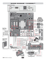
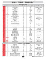
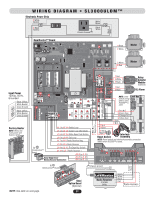
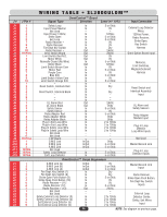
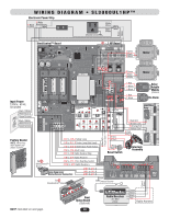
WIRING TABLE • SL3000UL™ J # J Pin # J1 1 J1 2 J1 3 J1 4 J1 5 J1 6 J1 7 J1 8 J1 9 J1 10 J2 10 Pins J3 1 J3 2 J3 3 J3 4 J3 5 J3 6 J3 7 J3 8 J3 9 J3 10 J5 1 J5 2 J5 3 J5 4 J5 5 J5 6 J5 7 J6 1 J6 2 J6 3 J6 4 J7 1 J7 2 J7 3 J8 1 J8 2 J8 3 J8 4 J8 5 J8 6 J9 16 Pins J10 1 J10 2 J10 3 J11 10 Pins J12 10 Pins J13 10 Pins J1 1 J1 2 J1 3 J2 1 J2 2 J2 3 J2 4 J2 5 J2 6 J2 7 J3 1 J3 2 J3 3 J3 4 J3 5 J3 6 OmniControl™ Board Signal Type Safety Loop Input Power Neutral Not Used Input Power 120Vac Strike Open Exit Loop Radio Receiver - Radio Receiver Fire Dept Key Switch Radio Receiver + Omni Option Board Limit Switch Red N.O. Motor White Normally Closed (No Wire) Motor Black Limit Switch Brown Com Motor Red Purple Com Blue N.O. Limit Switch Yellow Com Limit Switch Orange N.O. - Reset Switch, Interlock Red - Reset Switch, Interlock Black - - - UL Alarm Red UL Alarm Black Safety Sensor Safety Sensor Relay Adapter Red Relay Adapter White Relay Adapter Black Plug-In Exit Loop Wire Plug-In Exit Loop Wire Plug-In Safety Loop Wire Plug-In Safety Loop Wire Not Used Not Used 1 HP Board G M/S Link B M/S Link A M/S Link Not Used Safety Loop Detector Exit Loop Detector Direction In In - In In In In In In Out Out Out Out In Out In In In In In In In In In In In In In Out Out In In In In In In In In In - - - In/Out In/Out In/Out - In In Level (+/- 10%) 5 or 0Vdc 0V - 120Vac 5 or 0Vdc 5 or 0Vdc 0V 0V Dry 24Vdc 24Vdc 0V 0V 5 or 0Vdc 120Vac 0V 5 or 0Vdc 0V 5 or 0Vdc 0V 5 or 0Vdc - Dry - Dry - - - 24Vdc 0Vdc 5 or 0Vdc 0V 5 or 0Vdc 0Vdc 0Vdc 2 to 10Vdc 2 to 10Vdc 2 to 10Vdc 2 to 10Vdc - - - 0Vdc 5 or 0Vdc 5 or 0Vdc - 5 or 0Vdc 5 or 0Vdc Input Connection External Loop Detector Wires, 120Vac Power, Radio Receiver, Strike Open, Key Switch Harness Omni Option Board Input Motor(s), Limit Switches, Maglock/Solenoid Harness Reset Switch and Interlock Assembly Input UL Alarm and Safety Sensors Relay Adapter Module Input Plug-In Loop Detector Loop Wire Inputs Not Used Master/Second Link Plug-In Loop Detector Inputs OmniControl™ Surge Suppressor G M/S Link (G) B M/S Link (B) A M/S Link (A) Fire Dept. Key Switch (7) Fire Dept. Key Switch (8) Strike Open Push Button (9) Strike Open Push Button (10) Radio Receiver - (11) Radio Receiver (12) Radio Receiver + (13) Not Used Not Used Safety External Loop Detector (3) Safety External Loop Detector (4) Exit External Loop Detector (5) Exit External Loop Detector (6) In/Out In/Out In/Out In In In In In In Out - - In In In In 36 0V 5 or 0Vdc 5 or 0Vdc Dry Dry 5 or 0Vdc 0V 0V 5 or 0Vdc 24Vdc - - 2 to 10Vdc 2 to 10Vdc 2 to 10Vdc 2 to 10Vdc Master/Second Link Input Radio Receiver, Strike Open Push Button, Fire Dept Key Switch Inputs External Loop Detector Center, Safety, Exit Wires Input NOTE: See diagram on previous page.
-
 1
1 -
2
-
3
-
4
-
5
-
6
-
7
-
8
-
9
-
10
-
11
-
12
-
13
-
14
-
15
-
16
-
17
-
18
-
19
-
20
-
21
-
22
-
23
-
24
-
25
-
26
-
27
-
28
-
29
-
30
-
31
-
32
-
 33
33 -
 34
34 -
 35
35 -
 36
36 -
 37
37 -
 38
38 -
 39
39 -
 40
40 -
 41
41 -
 42
42 -
 43
43 -
44
-
45
-
46
-
47
-
48
-
49
-
50
-
51
-
52
 |
 |
