LiftMaster SL3000UL3 Owners Manual - Page 44
Wiring Table DC2000, Radio Receiver, Reset Switch, Manual Three Button, Manual Key Switch, 12Vdc
 |
View all LiftMaster SL3000UL3 manuals
Add to My Manuals
Save this manual to your list of manuals |
Page 44 highlights
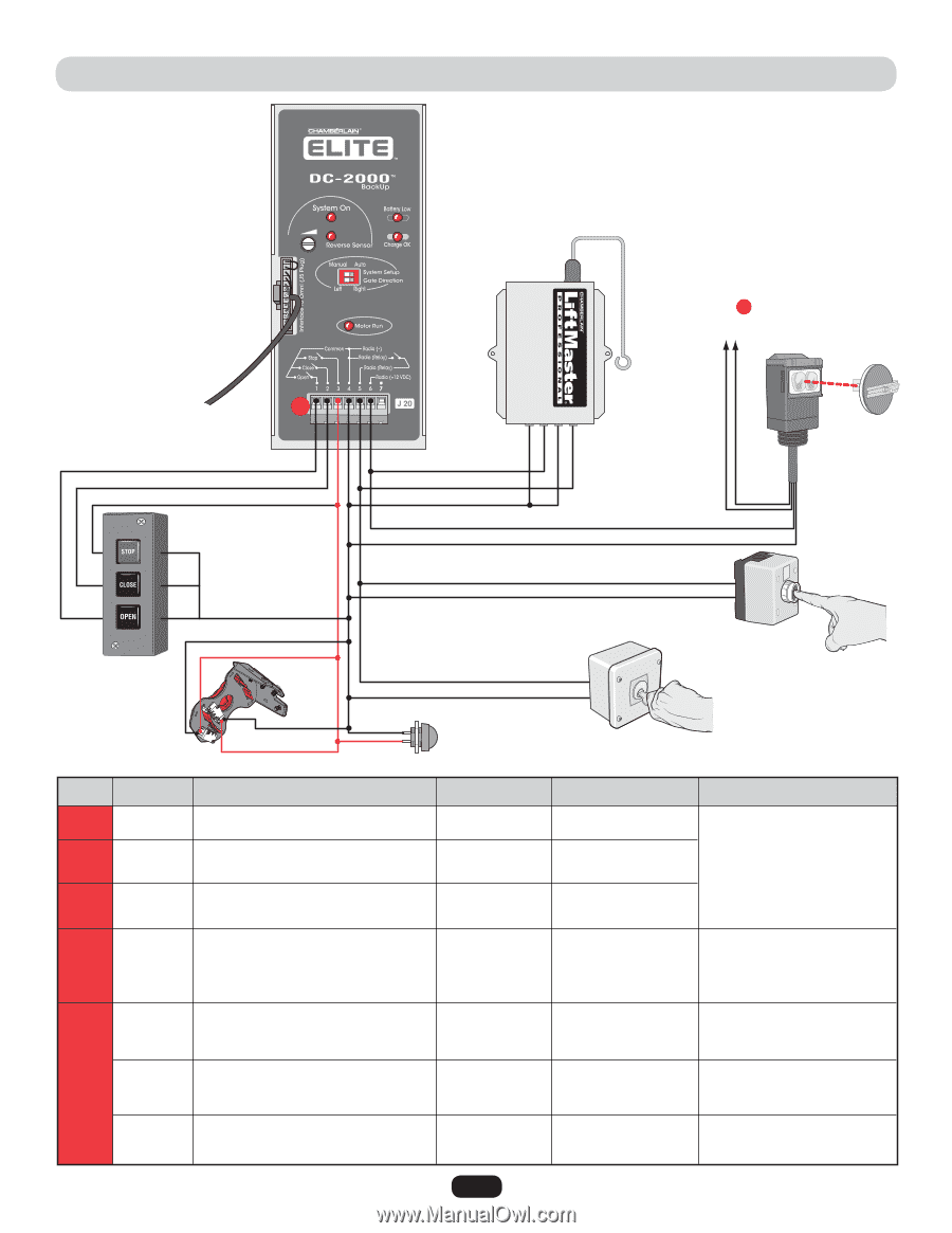
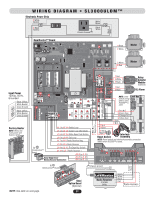
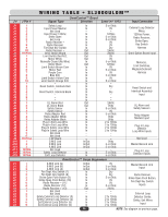
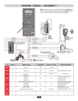
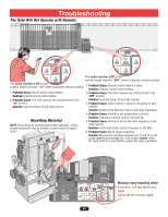
WIRING TABLE • DC2000™ NOTE: All devices wired to the DC2000™ MUST be dedicated to it alone. Normal operation will be controlled by separate devices wired to the OmniControl™ board and surge suppressor. Radio Receiver 315 MHz 12Vdc to J6 Pin 3,4 OmniControl™ Board (Sensor) 1 2 3 4 5 6 7 J20 1 Open N.O. 2 Close N.O. 3 Stop N.O. Manual Three Button Dry Contact 6 + 12Vdc 5 Radio Relay 4 - Radio 6 + 12Vdc 4 Photoelectric Sensor 12 34 12Vdc Radio Receiver 4 Common Black Com Red N.O. Interlock Assembly Black Com Red N.O. 5 One Button 4 One Button 5 Key Switch 4 Key Switch Manual Key Switch Dry Contact 4 Black 3 Red Reset Switch 12Vdc Photoelectric Sensor Manual One Button Dry Contact J # J Pin # J20 1 J20 2 J20 3 J20 4 J20 5 J20 6 Signal Type Open N.O. Close N.O. Stop N.O. Reset Switch Common Radio - Radio Relay Reset Switch/Interlock Assembly One Button Key Switch Radio Relay Radio + 12Vdc Photoelectric Sensor + 12Vdc Direction Out Out Out Out Out Out Level (+/- 10%) 5 or 0Vdc Input Connection 5 or 0Vdc • Manual Three Button (Dry) 5 or 0Vdc Reset Switch 0V 0V 12 or 0Vdc • Manual One Button (Dry) • Key Switch (Dry) • Radio Receiver Reset Switch/Interlock Assy • Manual One Button (Dry) • Key Switch (Dry) • Radio Receiver • Radio Receiver 12Vdc • Photoelectric Sensor 12Vdc J20 7 - - - - 42
-
 1
1 -
2
-
3
-
4
-
5
-
6
-
7
-
8
-
9
-
10
-
11
-
12
-
13
-
14
-
15
-
16
-
17
-
18
-
19
-
20
-
21
-
22
-
23
-
24
-
25
-
26
-
27
-
28
-
29
-
30
-
31
-
32
-
33
-
34
-
35
-
36
-
37
-
38
-
 39
39 -
 40
40 -
 41
41 -
 42
42 -
 43
43 -
 44
44 -
 45
45 -
 46
46 -
 47
47 -
 48
48 -
 49
49 -
50
-
51
-
52
 |
 |