Lowrance Elite-9 Ti Installation Manual EN - Page 29
Planning and installing a network backbone, Power the network, Purpose, Color
 |
View all Lowrance Elite-9 Ti manuals
Add to My Manuals
Save this manual to your list of manuals |
Page 29 highlights
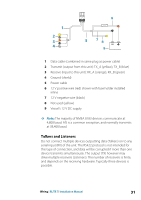
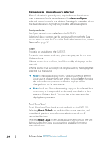
Key Purpose 4 NET-H 5 NET-L Color White Blue Planning and installing a network backbone The backbone needs to run between the locations of all products to be installed - typically in a bow to stern layout - and be no further than 6 m from a device to be connected. Choose from the following components to make up the backbone: • Micro-C cables: 0.6 m (2 ft), 1.8 m (6 ft), 4.5 m (15 ft), and 7.6 m (25 ft) cables. • T-connector or 4-way connector. Used to connect a drop cable to the backbone. • Micro-C power cable. Connect to the backbone at a position that is central to the network load using a T-connector or 4-way connector. Power the network The network requires its own 12 V DC power supply protected by a 3 amp fuse or breaker. Connect power at any location in the backbone for smaller systems. For larger systems introduce power at a central point in the backbone to balance the voltage drop of the network. Ú Note: If joining to an existing NMEA 2000 network that already has its own power supply, do not make another power connection elsewhere in the network, and ensure the existing network is not powered by 24 V DC. Ú Note: Do not connect the NMEA 2000 power cable to the same terminals as the engine start batteries, autopilot computer, bow thruster or other high current devices. The following drawing demonstrates a typical small network. The backbone is made up of directly interconnected T-connectors. Wiring | ELITE Ti Installation Manual 29
-
 1
1 -
2
-
3
-
4
-
5
-
6
-
7
-
8
-
9
-
10
-
11
-
12
-
13
-
14
-
15
-
16
-
17
-
18
-
19
-
20
-
21
-
22
-
23
-
 24
24 -
 25
25 -
 26
26 -
 27
27 -
 28
28 -
 29
29 -
 30
30 -
 31
31 -
 32
32 -
 33
33 -
 34
34 -
35
-
36
-
37
-
38
-
39
-
40
-
41
-
42
-
43
-
44
-
45
-
46
-
47
-
48
-
49
-
50
-
51
-
52
-
53
-
54
-
55
-
56
-
57
-
58
-
59
-
60
-
61
-
62
-
63
-
64
-
65
-
66
-
67
-
68
-
69
-
70
-
71
-
72
 |
 |
