MSI 865GVM2 User Guide - Page 31
IEEE 1394 Connector: J1394_1/J1394_2 Optional, How to attach the IEEE 1394 Port, IEEE1394 Bracket
 |
View all MSI 865GVM2 manuals
Add to My Manuals
Save this manual to your list of manuals |
Page 31 highlights
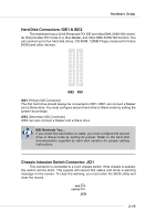
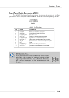
MS-7037 M-ATX Mainboard IEEE 1394 Connector: J1394_1/J1394_2 (Optional) The mainboard provides two 1394 pin headers that allow you to connect optional IEEE 1394 port. 9 1 10 2 J1394_1 / J1394_2 Pin Definition PIN SIGNAL PIN 1 TPA+ 2 3 Ground 4 5 TPB+ 6 7 Cable power 8 9 Key (no pin) 10 SIGNAL TPAGround TPBCable power Ground How to attach the IEEE 1394 Port: Connected to J1394_1 / J1394_2 Foolproof design IEEE1394 Bracket (Optional) 2-20
-
 1
1 -
2
-
3
-
4
-
5
-
6
-
7
-
8
-
9
-
10
-
11
-
12
-
13
-
14
-
15
-
16
-
17
-
18
-
19
-
20
-
21
-
22
-
23
-
24
-
25
-
 26
26 -
 27
27 -
 28
28 -
 29
29 -
 30
30 -
 31
31 -
 32
32 -
 33
33 -
 34
34 -
 35
35 -
 36
36 -
37
-
38
-
39
-
40
-
41
-
42
-
43
-
44
-
45
-
46
-
47
-
48
-
49
-
50
-
51
-
52
-
53
-
54
-
55
-
56
-
57
-
58
-
59
-
60
-
61
-
62
-
63
-
64
-
65
-
66
-
67
-
68
-
69
-
70
-
71
-
72
-
73
-
74
 |
 |
2-20
MS-7037 M-ATX Mainboard
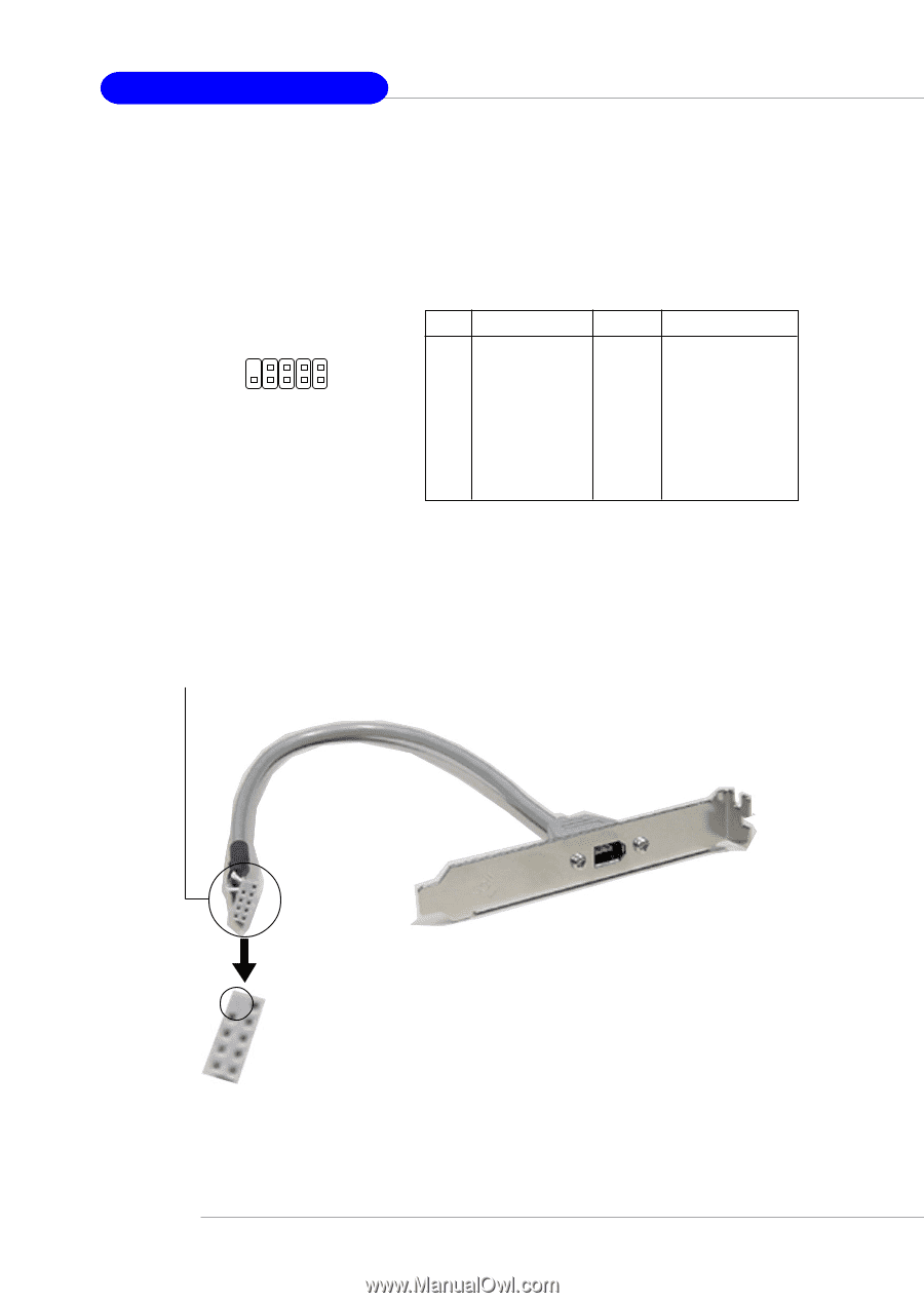
How to attach the IEEE 1394 Port:
Foolproof
design
Connected to J1394_1 / J1394_2
IEEE1394 Bracket
(Optional)
IEEE 1394 Connector: J1394_1/J1394_2 (Optional)
The mainboard provides two 1394 pin headers that allow you to connect
optional IEEE 1394 port.
J1394_1 / J1394_2
9
2
10
1
Pin Definition
PIN
SIGNAL
PIN
SIGNAL
1
TPA+
2
TPA-
3
Ground
4
Ground
5
TPB+
6
TPB-
7
Cable power
8
Cable power
9
Key (no pin)
10
Ground