MSI K7D MASTER User Guide
MSI K7D MASTER - Motherboard - ATX Manual
 |
UPC - 816909002010
View all MSI K7D MASTER manuals
Add to My Manuals
Save this manual to your list of manuals |
MSI K7D MASTER manual content summary:
- MSI K7D MASTER | User Guide - Page 1
MSI K7D Master K7D Master-L MICRO-STAR INTERNATIONAL MS-6501 (v1.X) ATX Mainboard Version 1.1 G52-MA00571 i - MSI K7D MASTER | User Guide - Page 2
frequency energy and, if not installed and used in accordance with the instruction manual, may cause harmful interference to radio communications. Operation of this equipment AVANT DE RACCORDER AU RESEAU. Micro-Star International MS-6501 Tested to comply with FCC Standard For Home or Office Use ii - MSI K7D MASTER | User Guide - Page 3
registered trademarks of International Business Machines Corporation. Windows® 95/98/2000/NT/XP are registered trademarks of Microsoft Corporation. Netware® is a registered trademark of Megatrends Inc. Revision History Revision V1.1 Revision History Add LAN, USB ports, JUSB1 Date March 2002 iii - MSI K7D MASTER | User Guide - Page 4
1. Read the safety instructions carefully. 2. Save this User's Guide for possible use later. 3. Keep this equipment away from shock. 11. If any of the following situations arises, get the equipment checked by a service personnel: z the power cord or plug is damaged z liquid has penetrated into the - MSI K7D MASTER | User Guide - Page 5
Specification 1-2 Mainboard Layout 1-4 Quick Components Guide 1-6 MSI Special Features 1-7 PC Alert™ III 1-7 Fuzzy Logic™ III 1-8 D-LED™&D-Bracket 1-9 Chapter 2. Hardware Setup 2-1 Central Processing Unit: CPU 2-2 CPU Installation Procedures 2-3 Thermal Issue for CPU 2-4 CPU Core - MSI K7D MASTER | User Guide - Page 6
Audio Port Connectors 2- LAN Connector: JWL1 2-21 CPUFAN1/CPUFAN2/PSFAN1/SYSFAN/NBFAN1 2-22 USB Front Panel Connector: JUSB1 2-23 D-Bracket™ Connector: JDB1 2- 2-28 AGP (Accelerated Graphics Port) Pro Slot 2-28 PCI Slots 2-28 PCI Interrupt Request Routing 2-29 Chapter 3. AWARD® BIOS Setup 3-1 - MSI K7D MASTER | User Guide - Page 7
Drivers A-1 Driver Installation for Windows 2000/XP A-2 Installing Intel Ethernet LAN Driver A-3 Installing AMD 762 Chipset Driver A-4 Installing AMD EIDE Driver A-6 Installing AMD 768 Chipset Driver A-9 LargePageMinimum A-10 AMD AC97 Audio Driver A-11 Appendix B: USB 2.0 Controller - MSI K7D MASTER | User Guide - Page 8
MSI mainboard. The MS-6501 V1.X ATX mainboard is an excellent computer mainboard based on the innovative AMD-762™ & 768™ chipsets, which supports the dual AMD Athlon™ MP processors series and provides you a cost-effective solution to meet your needs. TOPICS Mainboard Specification 1-2 Mainboard - MSI K7D MASTER | User Guide - Page 9
Specification CPU Supports dual Socket A (Socket-462) for AMD Athlon™ MP processors Supports Athlon MP 2100+ or higher Chipset AMD-762™ chipset (949 BGA) - Supports 200MHz High speed, split transaction system bus - A 66/33MHz 64/32bit PCI 2.2 compliant bus interface supports up to seven bus masters - MSI K7D MASTER | User Guide - Page 10
parallel port supports SPP/EPP/ECP mode - 4 USB ports (2 Rear Connectors / 2 Front Pin Headers) - 1 IrDA/HP connector for SIR/CIR/FIR/ASKIRHPSIR - 1 audio/game port Network (K7D Master-L) Intel® 82551QM LAN Controller - Integrated IEEE802.3 10-BaseT & 100-BaseTX PHY BIOS The mainboard BIOS provides - MSI K7D MASTER | User Guide - Page 11
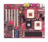
82551QM JPHN1 JAUX1 AGP Pro Slot AMD 762 J4 NBFAN1 Codec 64-bit PCI Slot 1 64-bit PCI Slot 2 32-bit PCI Slot 1 BATT + JWL1 32-bit PCI Slot 2 32-bit PCI Slot 3 AMD 768 JCI K7D Master-L ATX Mainboard (MS-6501 v1.X) DDR 1 DDR 2 DDR 3 DDR 4 S Y S FA N FDD1 IDE 1 IDE 2 BIOS JWR1 JFSB1 JUSB1 - MSI K7D MASTER | User Guide - Page 12
462 CPUFAN1 SOCKET 462 D-LED JDB1 Top : Game port Bottom: Line-Out Line-In Mic JCD1 JPHN1 JAUX1 AGP Pro Slot AMD 762 J4 NBFAN1 Codec BATT + JWL1 64-bit PCI Slot 1 64-bit PCI Slot 2 32-bit PCI Slot 1 32-bit PCI Slot 2 32-bit PCI Slot 3 AMD 768 JCI K7D Master ATX Mainboard (MS-6501 v1 - MSI K7D MASTER | User Guide - Page 13
Chapter 1 Quick Components Guide Component JFSB1 JPWR1 J4 JKBMS1 JKBMS1 COM A & COM B USB Connectors LAN Connector LPT1 FDD1 IDE1~ IDE2 JFP1/JFP2 JCD1 JAUX1 JPHN1 JWR1 JWL1 CPUFAN1/CPUFAN2/ SYSFAN/PSFAN1/NBFAN1 JUSB1 JDB1 JIR1 JCI1 JBAT1 AGP Pro Slot PCI Slots Function For CPU Clock Frequency ATX - MSI K7D MASTER | User Guide - Page 14
& D which are only available in MSI mainboards. PC Alert™ III The PC AlertTM III is an utility you can find in the CD-ROM disk. The utility is just like your PC doctor that can detect the following PC hardware status during real time operation: * monitor CPU & system temperatures * monitor fan speed - MSI K7D MASTER | User Guide - Page 15
Fuzzy Logic™ III utility allows users to overclock the CPU FSB (Front Side Bus) frequency in the Windows environment. Select the CPU frequency you prefer and click Go to Display Current System Status - CPU Fan - CPU Temp. - Vcore - Vio - Memory Clock - CPU Clock - AGP Clock - PCI Clock z Adjust - MSI K7D MASTER | User Guide - Page 16
the system, such as VGA, RAM or other failures. This special feature is very useful for the overclocking users. These users can use the feature to detect if there are any problems or failures. 1 2 3 4 Diagnostic LED The D-Bracket™ , which is an external USB bracket integrating four Diagnostic LEDs - MSI K7D MASTER | User Guide - Page 17
detect CPU clock and check the onboard video type, and then detect and initialize the video adapter. BIOS Sign -On - It will show information of the logo, brand name of the processor and so on. Testing Base and Extended Memory - It will test base memory from 240K to 640K and extended memory - MSI K7D MASTER | User Guide - Page 18
, the components will not work properly. Use a grounded wrist strap before handling computer components. Static electricity may damage the components. TOPICS Central Processing Unit: CPU 2-2 Memory 2-7 Power Supply 2-10 Back Panel 2-12 Connectors 2-17 Jumpers 2-27 Slots 2-28 2-1 - MSI K7D MASTER | User Guide - Page 19
Chapter 2 Central Processing Unit: CPU The MSI mainboard supports Single/Dual AMD® AthlonTM MP processor(s). The mainboard uses two CPU sockets called Socket A for easy CPU installation. You can install SINGLE or DUAL CPUs on the board to meet your own needs. Keep the following points in mind - MSI K7D MASTER | User Guide - Page 20
Installation Procedures 1. Pull the lever sideways away from the socket. Then, raise the lever up to a 90-degree angle. Sliding Plate Open Lever 2. Look for the cut edge. The cut edge should point towards the lever pivot. The CPU will only fit in the correct orientation. Cut edge 3. Hold the - MSI K7D MASTER | User Guide - Page 21
of high performance thermal interface material. AMD Athlon™ processor with a speed of 600MHz and above requires LARGER heatsink and fan. You also need to add thermal grease between the CPU and heatsink to improve heat dissipation. Then, make sure that the CPU and heatsink are securely fastened and - MSI K7D MASTER | User Guide - Page 22
core speed = Host Clock x Core/Bus ratio = 100MHzx7 = 700MHz CPU Clock Frequency Selection: JFSB1 The default hardware configuration for CPU Clock Frequency is set at 100 MHz. To use a 133 MHz CPU, you need to adjust the CPU clock up to 133 MHz by setting the JFSB1 jumper. 1 3 100MHz 1 3 133 - MSI K7D MASTER | User Guide - Page 23
accommodate the MS-6501 mainboard, Axial Fans and other required components, we recommend that you use the ATX computer case. To maintain a well-ventilated operating environment and prevent CPU overheating problems, we strongly suggest that you add two axial fans to the system. The specification of - MSI K7D MASTER | User Guide - Page 24
DDR 1 DDR 2 DDR 3 DDR 4 Hardware Setup Memory Installation The mainboard provides 4 sockets for 184-pin, 2.5V DDR DIMM with 8 memory banks. To operate properly, at least one DIMM module must be installed. DDR DIMM Slots (DDR 1~4) You can install PC1600/PC2100 DDR SDRAM modules on - MSI K7D MASTER | User Guide - Page 25
operation, at least one DIMM module must be installed on the mainboard. As the AMD-762TM chipset supports 4 DDR memory banks at its maximum, the system memory installed can be up to 4 GB. You can install memory modules in the following combination: Devices used on DIMM 64 MB (4Mx4x4 banks) 64 - MSI K7D MASTER | User Guide - Page 26
Hardware Setup DDR Module Installation Procedures You can install either single-sided or double-sided 184-pin DDR DIMM modules into DDR DIMM slots to meet your needs. Different from the SDR DIMM, the DDR DIMM has only one notch on the center of module. The number of pins on either side of the breaks - MSI K7D MASTER | User Guide - Page 27
is inserted in the proper orientation and the pins are aligned. Then push down the power supply firmly into the connector. The power connector supports instant power on function which means that system will boot up immediately when the power supply connector is inserted on the board. 10 20 1 11 - MSI K7D MASTER | User Guide - Page 28
. J4 4 2 3 1 Pin Definition PIN SIGNAL 1 GND 2 GND 3 12V 4 12V Note: Always make sure to connect a power cable to the J4 to provide power for the CPU & the AGP Pro card. Even if you do not intend to use AGP Pro card, you still have to connect the J4 in order to ensure that - MSI K7D MASTER | User Guide - Page 29
Chapter 2 Back Panel The Back Panel provides the following connectors: PS/2 Mouse RJ-45 LAN Port Parallel Port Joystick/MIDI PS/2Keyboard USB Ports 1 & 2 COM A COM B Line Out Line In Mic Mouse Connector: KBMS1 The mainboard provides a standard PS/2® mouse mini DIN connector for attaching a PS - MSI K7D MASTER | User Guide - Page 30
Hardware Setup Keyboard Connector: KBMS1 The mainboard provides a standard PS/2® keyboard mini DIN connector for attaching a PS/2® keyboard. You can plug a PS/2® keyboard directly into this connector. 6 5 PIN 1 4 3 2 3 4 21 5 6 PS/2 Keyboard (6-pin Female) Pin Definition SIGNAL - MSI K7D MASTER | User Guide - Page 31
Differential Pair Receive Differential Pair Not Used Not Used Receive Differential Pair Not Used Not Used 12 34 56 78 USB Ports USB Port Description PIN SIGNAL 1 VCC 2 -Data 0 3 +Data0 4 GND 5 VCC 6 -Data 1 7 +Data 1 8 GND DESCRIPTION +5V Negative Data Channel 0 Positive Data - MSI K7D MASTER | User Guide - Page 32
Port Connector: LPT1 The mainboard provides a 25-pin female centronic connector as LPT. A parallel port is a standard printer port that supports Enhanced Parallel Port (EPP) and Extended Capabilities Parallel Port (ECP) mode. 13 1 25 14 Pin Definition PIN SIGNAL DESCRIPTION 1 STROBE - MSI K7D MASTER | User Guide - Page 33
you choose to enable the Audio Multi-Channel, this will change the Line In to 3, 4 channel output and MIC to 5, 6 channel output (optional). To use this function, set the Audio Multi-Channel to enable located at the BIOS Integrated Peripherals or install the driver provided with this mainboard. 2-16 - MSI K7D MASTER | User Guide - Page 34
The mainboard provides connectors to connect to FDD, IDE HDD, case, modem, LAN, USB Ports, IR module and CPU/System FAN. Floppy Disk Drive Connector: FDD1 The mainboard provides a standard floppy disk drive connector that supports 360K, 720K, 1.2M, 1.44M and 2.88M floppy disk types. FDD1 2-17 - MSI K7D MASTER | User Guide - Page 35
Connector) - You can connect a Master and a Slave drive to IDE2. IDE 1 IDE 2 TIP: If you install two hard disks on cable, you must configure the second drive to Slave mode by setting its jumper. Refer to the hard disk documentation supplied by hard disk vendors for jumper setting instructions. 2-18 - MSI K7D MASTER | User Guide - Page 36
JFP1 and JFP2 allow you to connect to the Power Switch, Reset Swtich, Speaker, Power LED, and HDD LED on the case. Both JFP1 and JFP2 are compliant with Intel® Front Panel I/O Connectivity Design Guide. SPK BUZ 87 + - P LED + S - GND 21 JFP2 10 9 PWSW + RST + LED S P 21 - HDD - MSI K7D MASTER | User Guide - Page 37
2 CD-In Connector: JCD1 The connector is for CD-ROM audio connector. Aux Line-In Connector: JAUX1 The connector is for DVD add-on card with Line-in connector. Modem-In Connector: JPHN1 The connector is for modem with internal audio connector. JCD1 R GND L JPHN1 Phone_In GND Mono_Out JAUX1 R GND - MSI K7D MASTER | User Guide - Page 38
function. The connector will power up the system when a signal is received through the modem card. JWR1 is compliant with Intel® Front Panel I/O Connectivity Design Guide. 1 NC GND WOR (wake-up on ring) NC 5VSB JWR1 Wake On LAN Connector: JWL1 This connector allows you to connect to a LAN card with - MSI K7D MASTER | User Guide - Page 39
must use a specially designed fan with speed sensor to take advantage of the CPU fan control. GND +12V SENSOR CPUFAN2 SENSOR +12V GND PSFAN1 GND +12V Note: 1. Always consult the vendor for proper CPU cooling fan. 2. CPU Fan supports the fan control. You can install the PC Alert utility - MSI K7D MASTER | User Guide - Page 40
Panel Connector: JUSB1 The mainboard provides a Universal Serial Bus (USB) pin header that allows you to connect an optional USB port for front panel. JUSB1 is compliant with Intel® Front Panel I/O Connectivity Design Guide. 2 10 1 9 JUSB1 JUSB1 Pin Definition Pin Description Pin Description - MSI K7D MASTER | User Guide - Page 41
mainboard comes with a JDB1 connector for you to connect to DBracket™. D-Bracket™ is a USB Bracket integrating four LEDs whose functions are similar to D-LED™ and allows users to identify system problem through 16 various combinations of LED signals. For definitions of 16 signal combinations, please - MSI K7D MASTER | User Guide - Page 42
allows you to connect an IrDA Infrared module. You must configure the setting through the BIOS setup to use the IR function. JIR1 is compliant with Intel® Front Panel I/O Connectivity Design Guide. 26 15 JIR1 Pin Definition Pin Signal Description Pin Signal Description 1 NC Not Assigned - MSI K7D MASTER | User Guide - Page 43
switch will be short. The system will record this status and show a warning message on the screen. To clear the warning, you must enter the BIOS utility and clear the record. JCI1 is compliant with Intel® Front Panel I/O Connectivity Design - MSI K7D MASTER | User Guide - Page 44
how to change your motherboard's function through the use of the jumper. Clear CMOS Jumper: JBAT1 There is a CMOS RAM on board that has clear data. JBAT1 is compliant with Intel® Front Panel I/O Connectivity Design Guide. Follow the instructions below to clear the data: 1 3 Keep Data 1 3 Clear - MSI K7D MASTER | User Guide - Page 45
The motherboard provides one AGP Pro slot, three 32-bit master PCI bus slots, and two 64-bit master PCI bus slots. AGP Pro Slot 64-Bit PCI Slots 32-Bit PCI Slots AGP (Accelerated Graphics Port) Pro Slot The AGP Pro slot allows you to insert the AGP or AGP Pro graphics cards. The universal AGP Pro - MSI K7D MASTER | User Guide - Page 46
Hardware Setup PCI Interrupt Request Routing The IRQ, abbreviation of interrupt request line and pronounced I-R-Q, are hardware lines over which devices can send interrupt signals to the microprocessor. The PCI IRQ pins are typically connected to the PCI bus INT A# ~ INT D# pins as follows: PCI - MSI K7D MASTER | User Guide - Page 47
ASWetAupRD® BIOS Setup 3 If your motherboard comes with the AWARD® BIOS ROM, read this chapter for an overview of the Award® BIOS settings. AWARD® BIOS ROM provides a Setup utility for users to modify the basic system configuration. The information is stored in a battery-backed CMOS RAM so it - MSI K7D MASTER | User Guide - Page 48
Chapter 3 Entering Setup Power on the computer and the system will start POST (Power On Self Test) process. When the message below appears on the screen, press to enter Setup. Press to Enter SETUP If the message disappears before you respond and you still wish to enter Setup, restart the - MSI K7D MASTER | User Guide - Page 49
a sub-menu can be launched from 8IDE Primary Master this field. A sub-menu contains additional op- 8IDE Primary Slave tions for a field return to the main menu, just press the . General Help The BIOS setup program provides a General Help screen. You can call up this screen from any - MSI K7D MASTER | User Guide - Page 50
among the items and press to accept or enter the sub-menu. Standard CMOS Features Use this Menu for basic system configurations. Advanced BIOS Features Use this menu to set the Advanced Features available on your system. Advanced Chipset Features Use this menu to change the values in the - MSI K7D MASTER | User Guide - Page 51
This entry appears if your system supports PnP/PCI. PC Health Status This entry shows your PC health status. Frequency/Voltage Control Use this menu to specify your settings for frequency/voltage control. Load Fail-Safe Defaults Use this menu to load the BIOS default values for the minimal/stable - MSI K7D MASTER | User Guide - Page 52
function keys. year The year, depends on the year of the BIOS Time The time format is . IDE Primary/Secondary Master/Slave Press PgUp/ or PgDn/ to select Manual, None, Auto type. Note that the specifications of your drive must match with the drive table. The hard disk - MSI K7D MASTER | User Guide - Page 53
AWARD® BIOS Setup If you select Manual, related information is asked to be entered to the following items. Enter the a disk error. The system doesn't stop for either a disk or a keyboard error. Base/Extended/Total Memory The three items show the memory status of your system (read only). 3-7 - MSI K7D MASTER | User Guide - Page 54
function is enabled and someone attempts to write data into this area, BIOS will show a warning message on screen and alarm beep. Disabled No table. CPU Internal /External Cache Cache memory is additional memory that is much faster than conventional DRAM (system memory). When the CPU requests - MSI K7D MASTER | User Guide - Page 55
vice-versa. Boot Up Floppy Seek When this item is enabled during POST, BIOS will determine if the floppy disk drive installed is 40 or 80 tracks. 360K 64KB of extended memory. When the default value Fast is selected, the Gate A20 is controlled by Port 92 or chipset specific method resulting in - MSI K7D MASTER | User Guide - Page 56
Shadow Shadowing is a technique used to increase a computer's speed by using highspeed RAM memory in place of slower ROM memory. This setting enables/ disables the video BIOS to shadow into memory area C0000-C7FFF. Setting options: Disabled and Enabled. Small Logo(EPA) Show This item allows you - MSI K7D MASTER | User Guide - Page 57
. The settings are Enabled or Disabled. Video RAM Cacheable The field allows the caching of video memory, resulting in increased system performance. The settings are Enabled or Disabled. BIOS ID of MP Capabilities This item is to have the Athlon XP or MP processor running in multiprocessor mode - MSI K7D MASTER | User Guide - Page 58
disabled this MP feature in Athlon XP processors since 0.13 manufacturing process is applied. Therefore, this BIOS option is just a service to old AMD users and should not be considered as a solution to have Ahtlon XP processors working like Athlon MPs. Memory Hole At 15M-16M You can reserve this - MSI K7D MASTER | User Guide - Page 59
AWARD® BIOS Setup ongoing basis at regular intervals. AGP Secondary Lat Timer This allows you to set the AGP Secondary Lat Timer. The Scrub. Super Bypass Mode When enabled, the chipset internally bypasses certain memory to CPU pipe stages for optimal performance. The settings are: Disabled or Enabled - MSI K7D MASTER | User Guide - Page 60
data for faster performance. Settings are: Enabled and Disabled. Primary/Secondary Master/Slave PIO The four IDE PIO (Programmed Input/Output) fields let you each of the four IDE devices that the onboard IDE interface supports. Modes 0 through 4 provide successively increased performance. In Auto - MSI K7D MASTER | User Guide - Page 61
that does not support or have any USB driver installed, such as DOS and SCO Unix. The settings are: Enabled and Disabled. Init Display First This item specifies which VGA card is your primary graphics adapter. Settings are: PCI Slot and AGP. On-Chip AC97 Auto allows the motherboard's BIOS to detect - MSI K7D MASTER | User Guide - Page 62
block mode (most new drives do), select Enabled for automatic detection of the optimal number of block read/ writes per sector the drive can support. The settings are: Enabled, Disabled. POWER ON Function This controls how the PS/2 mouse or keyboard can power on the system. Settings are: Password - MSI K7D MASTER | User Guide - Page 63
AWARD® BIOS Setup RxD, TxD Active The item determines the active of RxD, TxD. Settings: [Hi, Hi], [Hi, Lo], [Lo, Hi] and [Lo, Lo]. IR Transmission Delay - MSI K7D MASTER | User Guide - Page 64
, 300, 290 Midi Port IRQ The item specifies an IRQ for the Midi port. Settings: 5, 10. Power Status LED You may choose either Single or Dual LED to show the power status. 3-18 - MSI K7D MASTER | User Guide - Page 65
AWARD® BIOS Setup Power Management Setup The Power Management Setup allows you to configure your system to most effectively save energy while S3. S1 (POS) The S1 sleeping state is low wake-up latency sleeping state. In this state, no system context is lost (CPU or chip set) and hardware main- 3-19 - MSI K7D MASTER | User Guide - Page 66
, and chipset context are lost in this state. Hardware maintains memory context and restores some CPU and L2 configuration context. Run VGABIOS if S3 Resume This item allows the system to initialize the VGA BIOS from S3 (Suspend to RAM) sleep state. Settings are: Auto, Yes and No. Power Management - MSI K7D MASTER | User Guide - Page 67
AWARD® BIOS Setup HDD Power Down When enabled and after the set saving mode whenever Modem Ring In event occurs. To use the WOL function, you need a LAN add-on card which support power on functions. Settings are: Enabled or Disabled. Modem Use IRQ This determines the IRQ in which the MODEM can use - MSI K7D MASTER | User Guide - Page 68
this by causing an IRQ to occur. After receiving the signal, when the operating system is ready, the system will interrupt itself and perform the service required by the I/O device. 3-22 - MSI K7D MASTER | User Guide - Page 69
AWARD® BIOS Setup PNP/PCI Configurations This section describes configuring the PCI bus system. PCI, or Peripheral Component Interconnect, is a system which allows I/O devices to operate at speeds nearing the speed the CPU itself uses when communicating with its own special components. This section - MSI K7D MASTER | User Guide - Page 70
enabled only when Resources Controlled By is set to Manual. Press and you will enter the requiring a specific interrupt. PCI/VGA Palette Snoop When set to Enabled, multiple VGA devices operating on different buses can handle data from the CPU on and BIOS default values are Disabled. 3-24 - MSI K7D MASTER | User Guide - Page 71
AWARD® BIOS Setup PC Health Status This section is to monitor the current hardware status including CPU temperature, CPU Fan thermal limit for CPU. If CPU temperature reaches the specified limit, the system will issue a warning which allows you to prevent the CPU overheat problem. Settings: Disabled - MSI K7D MASTER | User Guide - Page 72
provides a tool for users to overclock the processor. Settings are: Auto, x5 through x12.5. Note: This mainboard does not support CPU ratio over 12.5. That means, no overclocking option over 12.5 is allowed. The mainboard will recognize all series of Athlon/Duron processor speed, including FSB and - MSI K7D MASTER | User Guide - Page 73
AWARD® BIOS Setup CPU VIO/Vcore (V) This item allows users to auto-detect or specify the CPU VIO/Vcore. Settings are: 1.850 (V) through 1.100 (V), Auto. 3-27 - MSI K7D MASTER | User Guide - Page 74
Optimized values. The Optimized Defaults are the default values set by the mainboard manufacturer specifically for the optimal performance of the mainboard. The Fail-Safe Defaults are the default values set by the BIOS vendor for the stable system performance. When you select Load Fail-Safe Defaults - MSI K7D MASTER | User Guide - Page 75
AWARD® BIOS Setup Set Supervisor/User Password When you select this function, a message as below will appear on the screen: Type the password, up to eight characters in length, and press . The password typed now will replace any previously set password from CMOS memory. You will be prompted - MSI K7D MASTER | User Guide - Page 76
Installing Drivers A Appendix B: MSI Smart Key Installing Drivers This chapter describes how to install AMD chipsets and audio drivers under Windows 2000 and XP. When you do the installation, you should always install chipset drivers prior to the audio driver. Please note that the procedures and the - MSI K7D MASTER | User Guide - Page 77
drive. 2. The system will automatically read the CD and the MSI Installer dialog box will appear on the screen as shown below. 3. Refer to the instructions mentioned later in this chapter to complete the driver installation. Note: Remember to instll the chipset drivers prior to the audio driver. A-2 - MSI K7D MASTER | User Guide - Page 78
Driver for Windows 2000/XP 1. Click Intel Ethernet Driver. 2. The following dialog box will appear on the screen. Click Yes to con tinue installing the driver on your system. 3. Click Yes to exit the Intel Ethernet Driver Setup. Return to the MSI Installer dialog box for AMD 762 Chipset Driver - MSI K7D MASTER | User Guide - Page 79
AMD 762 Chipset Driver for Windows 2000/XP 1. Click AMD 762 Chipset. 2. The following Welcome to AMD AGP Filter Driver Setup Program dialog box will appear on the screen. Click Next to continue the Setup program. 3. The Installation Complete dialog box informs you that AMD AGP Filter Driver - MSI K7D MASTER | User Guide - Page 80
Installing Drivers 4. The system will ask you to click OK to restart the computer or Cancel to return to Windows. Click Cancel to procede with the AMD EIDE Driver installation. A-5 - MSI K7D MASTER | User Guide - Page 81
Appendix A Installing AMD EIDE Driver for Windows 2000/XP 1. Click AMD EIDE Driver. 2. Select your desired language in the Select Language list and then click OK to procede to the next step. 3. The AMD Bus Master IDE Driver Setup program dialog box will appear on the screen. Click Next to continue. - MSI K7D MASTER | User Guide - Page 82
Installing Drivers 4. Read the terms and conditions in the License Agreement dialog box. Click I Agree and then Next to continue. 5. The Start Installation dialog box will appear on the screen. Click Next to start installing the AMD Bus Master IDE Driver. A-7 - MSI K7D MASTER | User Guide - Page 83
Complete dialog box informs you that AMD Bus Master IDE Driver has been successfully installed. Click Finish to continue. 7. The system will ask you to click OK to restart the computer or Cancel to return to Windows. Click Cancel to procede with the AMD 768 Chipset Driver installation. A-8 - MSI K7D MASTER | User Guide - Page 84
Installing Drivers Installing AMD 768 Chipset Driver for Windows 2000/XP 1. Click AMD 768 Chipset. 2. The Welcome to AMD PM INF Installation Setup program dialog box will appear on the screen. Click Next to procede to the next step. 3. The Installation Complete dialog box - MSI K7D MASTER | User Guide - Page 85
will ask you to click OK to restart the computer or Cancel to return to Windows. Click Cancel to continue with the AMD 768 Chipset Driver installation. Installing LargePageMinimum (for Windows 2000 only) 1. Click LargePageMinimum. 2. The following dialog box will appear on the screen. Click Yes to - MSI K7D MASTER | User Guide - Page 86
Installing Drivers Installing AMD AC97 Audio Driver for Windows 2000/XP 1. Click AMD AC97 Audio Driver. 2. The Welcome to AC97 Setup program dialog box will appear on the screen. Click Next to continue installing the driver on your system. 3. Read the terms and conditions in the License Agreement - MSI K7D MASTER | User Guide - Page 87
Appendix A 4. The Read Me File dialog box shows that installing AC97AMD.INF file enables AC'97 Aduio for the AMD-768 Controlloer. Click Next to continue with the setup program. 5. Click Next to begin the installation. A-12 - MSI K7D MASTER | User Guide - Page 88
6. The progress indicator displays the percentage of the AMD AC97 Audio Driver installation that has been completed. 7. The Installation Complete dialog box will inform you that AC'97 has been successfully installed. Click Finish to exit the - MSI K7D MASTER | User Guide - Page 89
Controller Card B Appendix B: MSI Smart Key USB 2.0 Controller Card (optional) This chapter provides you the information about USB Controller Card. You will find detailed description of its features, system requirements, package contents, and hardware/software installation procedures. While doing - MSI K7D MASTER | User Guide - Page 90
Appendix B Acknowledgements IBM, and OS/2 are registered trademarks of International business Machines Corporation. Intel and Pentium are registered trademarks of Intel Corporation. Microsoft and Windows are registered trademarks of Microsoft Corporation. All other brand names and trademarks used - MSI K7D MASTER | User Guide - Page 91
USB 2.0 Controller Card FCC NOTICE This equipment has been tested and found to comply with and can radiate radio frequency energy and if not installed and used in accordance to the instructions, may cause harmful interference to radio communications. However, there is no guarantee that interference - MSI K7D MASTER | User Guide - Page 92
speed signaling and works up to 480Mbps. 5 Port USB Card V2.0 is integrated 3 Host controller cores with PCI interface and USB 2.0 transceivers into a single chip. 5 Port USB Card V2.0 fully meets PCI specification V2.2. It is fully supported by USB operating system; such as Windows® OS platform. It - MSI K7D MASTER | User Guide - Page 93
USB 2.0 Controller Card System Requirements * IBM-compatibe PC * Available PCI Slot * Windows 98SE/ME/2000/XP * 586/133 CPU and 32 MB RAM or faster B-5 - MSI K7D MASTER | User Guide - Page 94
Appendix B Hardware Installation Figure 1: USB Controller Card Layout USB1 USB2 USB3 USB4 NEC D720100AGM USB5 USB Ports 1~4 (Type A) 1 2 3 4 USB5 Connector (Type A) 5 1 10 6 USB Connector Type B Type A Figure 2. USB1~5 Pin Definition Pin Signal 1/6 VCC 2/7 DATA- 3/8 DATA+ 4/9 - MSI K7D MASTER | User Guide - Page 95
IRQ, or DIP switch to set. Windows® 98SE Setup 1. Windows will auto-detect the USB Card and display a dialog "New Hardware found" during system boot up. Press "Next" on , system will require to install respective driver three times. Don't be confused and follow subsequent procedures. 2. Select "Search - MSI K7D MASTER | User Guide - Page 96
Appendix B 3. Click "Next". 4. Click "Next". 5. Click "Next". 6. Click "Finish". B-8 - MSI K7D MASTER | User Guide - Page 97
USB 2.0 Controller Card 7. Windows will auto-detect the USB Card and display a dialog "New Hardware found" during system boot up. Press "Next" on "Add New hardware Wizard" screen. 8. Select "Search for the best driver for your device(Recommended)" and click "Next". 9. Click "Next". B-9 - MSI K7D MASTER | User Guide - Page 98
Appendix B 10. Click "Next". 11. Click "Next". 12. Click "Finish". B-10 - MSI K7D MASTER | User Guide - Page 99
on the "Add New Hardware Wizard" screen. 14. Select "Search for the best driver for your device(Recommended)" and click "Next". 15. Click "Specify a location" and insert the installation CD into the CDROM drive. Browse to D:\USB\USB20\NEC (assuming D is the CDROM drive), and then click "Next". B-11 - MSI K7D MASTER | User Guide - Page 100
Appendix B 16. Click "Next" to continue. 17. Click "Next" to continue. 18. Click "Finish". B-12 - MSI K7D MASTER | User Guide - Page 101
USB 2.0 Controller Card 19. When "Device Manager" shows dual of "NEC USB Open Host Controller" and "MSI USB Enhanced Host Controller", that means the driver is successfully installed. B-13 - MSI K7D MASTER | User Guide - Page 102
Appendix B Windows® ME Setup 1. Windows ME supports Port (Plug-n-Play) mode and will install the USB Card driver automatically. Please insert the WinME source CD disk, click "Browse..." to choose "CD-ROM", and then click "OK". 2. Windows will detect the USB Card and display a dialog, "New Hardware - MSI K7D MASTER | User Guide - Page 103
4. Click "Next". USB 2.0 Controller Card 5. Click "Finish". 6. When the "Device Manager" shows dual of "NEC USB Open Host Controller (E13+)" and "NEC PCI to USB Enhanced Host Controller", that means the driver is successfully installed. B-15 - MSI K7D MASTER | User Guide - Page 104
Appendix B Windows® 2000 Setup 1. Windows 2000 supports Port (Plug-n-Play) mode and will install the USB Card driver directly. Windows will detect the USB Card and display a dialog "New Hardware found" during system boot up. Press "Next" on the "Found New Hardware Wizard" screen. 2. Select "Search - MSI K7D MASTER | User Guide - Page 105
USB 2.0 Controller Card 4. Click "Next". 5. Click "Finish". B-17 - MSI K7D MASTER | User Guide - Page 106
installed. Windows® XP Setup 1. Windows XP supports Port (Plug-n-Play) mode and will install the USB 2.0 Card driver directly. 2. Windows XP will auto-detect the USB 2.0 Card and display a dialog "New Hardware found" during system boot up. Press "Install from a list or specific location [Advanced - MSI K7D MASTER | User Guide - Page 107
USB 2.0 Controller Card 3. Select "Include this location in the search" and insert the CD disk. Click "Browse..." to choose "CD-ROM" and then click "Next". 4. Click "Continue Anyway". 5. Click "Finish". B-19 - MSI K7D MASTER | User Guide - Page 108
Appendix B 6. When the "Device Manager" shows dual of "NEC PCI to USB Open Host Controller" and "NEC PCI to USB Enhanced Host Controller", that means the driver is successfully installed. B-20 - MSI K7D MASTER | User Guide - Page 109
specification enables the OS (operating system) to control the amount of power given to each device attached to the computer. Windows 98/98SE, Windows 2000 and Windows ME can fully support ACPI to allow users managing the system power flexibly. AGP The BIOS CPU and main memory. Cache A special memory - MSI K7D MASTER | User Guide - Page 110
to represent a bit. As the development of technology, the memory type and specification used in computer becomes variety, such as SDRAM, DDR SDRAM, and RDRAM. For further instruction, please see the table below: Dynamic RAM (DRAM) Memory Technologies Type First Used FPM (60,70ns) 1990 EDO (50 - MSI K7D MASTER | User Guide - Page 111
Memory (error correcting code memory) A type of memory ) specification. IEEE 1394 A new, high speed external bus standard, also known as FireWire or iLink, which supports data as disk drivers. LPT (line printer terminal) Logical device name for a line printer; a name reserved by the MS-DOS for - MSI K7D MASTER | User Guide - Page 112
and Play) A set of specifications that allows a PC to configure itself automatically to work with peripherals. The user can "plug" in a peripheral device and "play" it without configuring the system manually. To implement this useful feature, both the BIOS that supports PnP and a PnP expansion card
-
 1
1 -
 2
2 -
 3
3 -
 4
4 -
 5
5 -
 6
6 -
 7
7 -
8
-
9
-
10
-
11
-
12
-
13
-
14
-
15
-
16
-
17
-
18
-
19
-
20
-
21
-
22
-
23
-
24
-
25
-
26
-
27
-
28
-
29
-
30
-
31
-
32
-
33
-
34
-
35
-
36
-
37
-
38
-
39
-
40
-
41
-
42
-
43
-
44
-
45
-
46
-
47
-
48
-
49
-
50
-
51
-
52
-
53
-
54
-
55
-
56
-
57
-
58
-
59
-
60
-
61
-
62
-
63
-
64
-
65
-
66
-
67
-
68
-
69
-
70
-
71
-
72
-
73
-
74
-
75
-
76
-
77
-
78
-
79
-
80
-
81
-
82
-
83
-
84
-
85
-
86
-
87
-
88
-
89
-
90
-
91
-
92
-
93
-
94
-
95
-
96
-
97
-
98
-
99
-
100
-
101
-
102
-
103
-
104
-
105
-
106
-
107
-
108
-
109
-
110
-
111
-
112
 |
 |

i
Version 1.1
G52-MA00571
MS-6501 (v1.X) ATX Mainboard
MSI
MICRO-STAR INTERNATIONAL
K7D Master
K7D Master-L