MSI P6N Diamond User Guide
MSI P6N Diamond - Motherboard - ATX Manual
 |
UPC - 816909039429
View all MSI P6N Diamond manuals
Add to My Manuals
Save this manual to your list of manuals |
MSI P6N Diamond manual content summary:
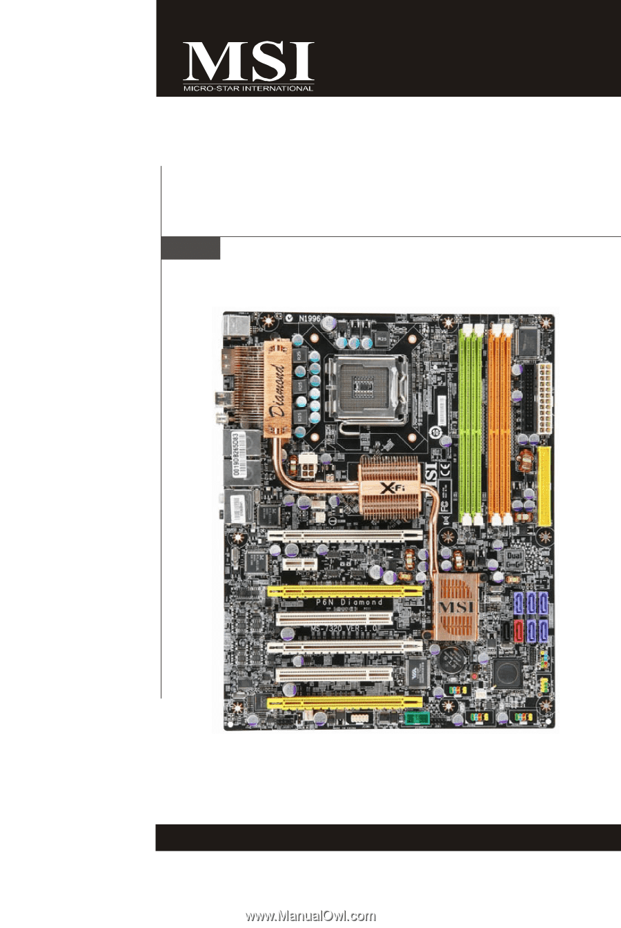
- MSI P6N Diamond | User Guide - Page 1
P6N Diamond series MS-7320 (V1.X) Mainboard G52-73201X1 i - MSI P6N Diamond | User Guide - Page 2
, please try the following help resources for further guidance. Visit the MSI website for FAQ, technical guide, BIOS updates, driver updates, and other information: http://www.msi.com.tw/program/service/faq/ faq/esc_faq_list.php Contact our technical staff at: http://support.msi.com.tw/ ii - MSI P6N Diamond | User Guide - Page 3
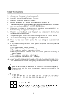
instructions carefully. 2. Keep this User's Manual for future reference. 3. Keep this equipment away from humidity. 4. Lay this equipment on a reliable flat surface before setting of the following situations arises, get the equipment checked by service personnel: † The power cord or plug is damaged. - MSI P6N Diamond | User Guide - Page 4
been tested and found to comply with the limits for a Class B digital device, pursuant to Part 15 of the FCC Rules. These limits are designed to provide and, if not installed and used in accordance with the instructions, may cause harmful interference to radio communications. However, there is - MSI P6N Diamond | User Guide - Page 5
WEEE (Waste Electrical and Electronic Equipment) Statement v - MSI P6N Diamond | User Guide - Page 6
vi - MSI P6N Diamond | User Guide - Page 7
vii - MSI P6N Diamond | User Guide - Page 8
Power Management Setup 3-13 PNP/PCI Configurations 3-16 H/W Monitor ...3-18 Cell Menu ...3-19 Load Fail-Safe/ Optimized Defaults 3-23 BIOS Setting Password 3-24 Appendix A Creative Sound Blaster A-1 Hardware Setup A-2 Installing the Creative Audio Driver A-6 Software Configuration A-8 viii - MSI P6N Diamond | User Guide - Page 9
Appendix B nVidia RAID B-1 Introduction ...B-2 RAID Configuration B-3 NVIDIA RAID Utility Installation B-9 RAID Drives Management B-12 Appendix C nVidia System Driver C-1 nVidia System Driver Installation C-2 nVidia Utility Installation C-5 Appendix D Dual Core Center D-1 Activating Dual - MSI P6N Diamond | User Guide - Page 10
Getting Started Chapter 1 Getting Started Thank you for choosing the P6N Diamond Series (MS7320 V1.X) ATX Mainboard. The P6N Diamond Series mainboards are based on nVIDIA® nForce 680i SLI & nForce 590i SLI chipsets for optimal system efficiency. Designed to fit the advanced Intel® Core 2 Extreme, - MSI P6N Diamond | User Guide - Page 11
/100/66/33 operation modes - Supports up to 2 IDE devices SATA - 5 SATA ports (SATA1~5) by nForce 590i SLI - 2 SATA ports (SATA6~7) by Sil4723 - Supports transfer rate up to 300 MB/s - 1 external-SATA port by Sil 3531 (back panel) RAID - SATA1~5 support RAID 0 or 1, 0+1, 5 or JBOD mode SiliconImage - MSI P6N Diamond | User Guide - Page 12
3 USB 2.0 pinheaders - 1 D-Bracket 2 pinheader - 1 IEEE 1394 pinheader - 1 Serial Port pinheader - 1 SPDIF pinheader (for HDMI VGA Card) - 1 Front Panel Audio pinheader - 2 hardware RAID Switch pinheaders Slots - 4 PCI Express x16 slots a.4 PCIE x16 slots support the latest Quad SLI * Quad SLI Mode - MSI P6N Diamond | User Guide - Page 13
SLI PCI 1 nVIDIA Nf590i SLI D IM M1 D IM M2 D IM M3 D IM M4 IDE1 S ATA 4 S ATA 3 S ATA 5 PCI _E4 PCI 2 Audio chip PCI _E5 SYSFAN1 JAUD1 SPDO1 JCOM1 VIA VT6308P B AT T + SW3 SATA7 SATA6 Silicon Sil4723 J U S B3 PW RFAN1 JFP1 JFP2 J139 4_1 JDB1 JU S B 2 J U SB 1 P6N Diamond Series - MSI P6N Diamond | User Guide - Page 14
Packing Checklist Getting Started MSI motherboard MSI Driver/Utility CD SLI Video Link Cable Power Cable SATA Cable Round Cable of IDE Devices Round Cable of Floppy Disk (Optional) D-Bracket 2 (Optional) 1394 Bracket (Optional) external SATA Cable (Optional) User's Guide Back IO Shield - MSI P6N Diamond | User Guide - Page 15
Hardware Setup Chapter 2 Hardware Setup This chapter provides you with the information about hardware setup procedures. While doing the installation, be careful in holding the components and follow the installation procedures. For some components, if you install in the wrong orientation, the - MSI P6N Diamond | User Guide - Page 16
MS-7320 Mainboard Quick Components Guide Back Panel I/O, p.2-11 JPW1, p.2-9 CPUFAN1, p.2-16 NBFAN1, p.2-16 PCI Express Slots, p.2-23 PCI Slots, p.2-26 CPU, p.2-3 DDR2 DIMMs, p.2-7 JCI1, p.2-16 FDD1, p.2-13 ATX1, p.2-9 IDE1, p.2-13 JP1~2, p.2-15 SATA1~7, p.2-14 JFP1~2, p.2-20 PWRFAN1, p.2-16 - MSI P6N Diamond | User Guide - Page 17
setting, while doing overclocking. Any attempt to operate beyond product specifications is not recommended. We do not guarantee the damages or risks caused by inadequate operation or beyond product specifications. Introduction to LGA 775 CPU The pin-pad side of LGA 775 CPU. The surface of LGA 775 - MSI P6N Diamond | User Guide - Page 18
installing the heat sink/cooler fan for better heat dispersion. Follow the steps below to install the CPU & cooler correctly. W rong installation will cause the damage of your CPU & mainboard. 1. The CPU socket has a plastic cap on it to protect the contact from damage. Before you install the - MSI P6N Diamond | User Guide - Page 19
Lift the load lever up and open the load plate. Hardware Setup 6. After confirming the CPU direction for correct mating, put down the CPU in the socket housing frame. Be sure to grasp on the edge of the CPU base. Note that the alignment keys are matched. alignment key 7. Visually inspect if the - MSI P6N Diamond | User Guide - Page 20
over the mainboard to confirm that the clip-ends are correctly inserted. locking switch Important 1. Read the CPU status in BIOS (Chapter 3). 2. Whenever CPU is not installed, always protect your CPU socket pin with the plastic cap covered (shown in Figure 1) to avoid damaging. 3. Mainboard photos - MSI P6N Diamond | User Guide - Page 21
Hardware Setup Memory These DIMM slots are used for installing memory modules. For more information on compatible components, please visit http://www.msi.com.tw/ testreport.htm DDR2 240-pin, 1.8V 56x2=112 pin 64x2=128 pin Dual-Channel Memory Population Rules In Dual-Channel mode, the memory - MSI P6N Diamond | User Guide - Page 22
are not interchangeable with DDR and the DDR2 standard is not backwards compatible. You should always install DDR2 memory modules in the DDR2 DIMM slots type and density in different channel DIMM slots. - To enable successful system boot-up, always insert the memory modules into the DIM M1 first. - - MSI P6N Diamond | User Guide - Page 23
21 +5V 10 +12V 22 +5V 11 +12V 23 +5V 12 +3.3V 24 GND pin 13 pin 12 ATX 12V Power Connector: JPW1 This power connector is used to provide power to the CPU. JPW1 4 8 1 5 Pin Definition PIN SIGNAL PIN SIGNAL 1 GND 2 GND 3 GND 4 GND 5 +12V 6 +12V 7 +12V 8 +12V Important 1. Make - MSI P6N Diamond | User Guide - Page 24
MS-7320 Mainboard Important Notification about Power Issue NForce chipset is very sensitive to ESD (Electrostatic to ESD, so this kind of memory-replacement actions might cause system chipset unable to boot. Please follow the following solution to avoid this situation. Unplug the AC power cable ( - MSI P6N Diamond | User Guide - Page 25
to IEEE1394 devices. S/PDIF-Out(Coaxial) This SPDIF (Sony & Philips Digital Interconnect Format) connector is provided for digital audio transmission to selected. USB Port The USB (Universal Serial Bus) port is for attaching USB devices such as keyboard, mouse, or other USB-compatible devices. 2-11 - MSI P6N Diamond | User Guide - Page 26
for microphones. Line In, is used for external CD player, tapeplayer or other audio devices. S/PDIF-Out (Optical) This SPDIF (Sony & Philips Digital Interconnect Format) connector is provided for digital audio transmission to external speakers through an optical fiber cable. Important Use only one - MSI P6N Diamond | User Guide - Page 27
drives, optical disk drives and other IDE devices. IDE1 Important If you install two IDE devices on the same cable, you must configure the drives separately to master / slave mode by setting jumpers. Refer to IDE device's documentation supplied by the vendors for jumper setting instructions. 2-13 - MSI P6N Diamond | User Guide - Page 28
connector can connect to one Serial ATA device. SATA4 SATA3 SATA5 SATA7 SATA6 SATA1 SATA2 support RAID function only. Please install two hard drives to SATA7 and SATA6 for RAID function. 3. The SATA6 and SATA7 are controlled by silicon image chip that supports RAID 0/ RAID 1 mode by hardware setting - MSI P6N Diamond | User Guide - Page 29
, JP2 These connectors are used to set RAID mode for the hard drives that connected to SATA6, SATA7. JP1 JP2 JP1 JP2 shorting JP1 = RAID 0 mode JP1 JP2 shorting JP1 & JP2 = RAID 1 mode Important When two hard drives are installed to SATA6 and SATA7 for RAID function, the indicator LED beside - MSI P6N Diamond | User Guide - Page 30
Important 1. Please refer to the recommended CPU fans at processor's official website or consult the vendors for proper CPU cooling fan. 2. CPUFAN1 supports fan control. You can install Dual screen. To clear the warning, you must enter the BIOS utility and clear the record. 2 GND 1 CINTRU JCI1 2-16 - MSI P6N Diamond | User Guide - Page 31
Connector: JAUD1 This connector allows you to connect the front panel audio and is compliant with Intel® Front Panel I/O Connectivity Design Guide. 9 1 JAUD1 10 2 PIN SIGNAL 1 FP-MICIN 2 GND 3 FP-VREFOUT 4 NC 5 LINE out_R 6 MIC_JD 7 GND 8 NC 9 LINE out_L 10 LINEout_JD Pin - MSI P6N Diamond | User Guide - Page 32
Connector: JUSB1 / JUSB2 / JUSB3 This connector, compliant with Intel® I/O Connectivity Design Guide, is ideal for connecting high-speed USB interface peripherals such as USB HDD, digital cameras, MP3 players, printers, modems and the like. 2 10 1 9 JUSB1~3 Pin Definition PIN SIGNAL 1 VCC - MSI P6N Diamond | User Guide - Page 33
IEEE1394 Connector: J1394_1 This connector allows you to connect the IEEE1394 device via an optional IEEE1394 bracket. 9 1 10 2 J1394_1 (The communication port that sends/receives 16 bytes FIFOs. You can attach a serial device. 2 1 9 JCOM1 Pin Definition PIN SIGNAL 1 DCD 2 SIN - MSI P6N Diamond | User Guide - Page 34
are for electrical connection to the front panel switches and LEDs. The JFP1 is compliant with Intel® Front Panel I/O Connectivity Design Guide. JFP1 10 Power Switch + Power LED 2 9 +Reset - Switch - HDD 1 + LED JFP1 Pin Definition PIN SIGNAL 1 HD_LED + 2 FP PW R/SLP 3 HD_LED - 4 FP - MSI P6N Diamond | User Guide - Page 35
VGA BIOS 1 2 Initializing Floppy Drive Controller This will start writing VGA sign-on This will initialize Floppy Drive and 3 4 message to the screen. 3 4 controller. 1 Processor Initialization 2 This will show information regarding 1 2 BootAttempt This will set low stack and boot via - MSI P6N Diamond | User Guide - Page 36
will explain how to change your motherboard's function through the use of button. Clear CMOS Button: SW3 There is a CMOS RAM on board that has a power supply from external battery to keep the system configuration data. With the CMOS RAM, the system can automatically boot OS every time it is turned - MSI P6N Diamond | User Guide - Page 37
1 supports up to 250 MB/s transfer rate. PCI Express x16 slot PCI Express x1 Slot Important When adding or removing expansion cards, make sure that you unplug the power supply first. Meanwhile, read the documentation for the expansion card to configure any necessary hardware or software settings for - MSI P6N Diamond | User Guide - Page 38
card. To utilize this technology, the two GPU cards must be connected by an SLI Video Link cable. SLI Video Link cable If you intend to use the SLI mode for better graphics performance, please refer to the following instructions. 1.Install two graphics cards on PCI Express x16 slots. W ith two cards - MSI P6N Diamond | User Guide - Page 39
and install the NV SLI driver/utility. A configuration panel will be provided for Multi-GPU control. Check the Enable multi-GPU box to enable the SLI function for the onboard graphics cards (concerning the details of multi-GPU settings, please refer to your graphics card manual) . Check the box - MSI P6N Diamond | User Guide - Page 40
MS-7320 Mainboard PCI (Peripheral Component Interconnect) Slots The PCI slots support LAN cards, SCSI cards, USB cards, and other add-on cards that comply with PCI specifications. At 32 bits and 33 MHz, it yields a throughput rate of 133 MBps. 32- - MSI P6N Diamond | User Guide - Page 41
information on the BIOS Setup program and allows you to configure the system for optimum use. You may need to run the Setup program when: ² An error message appears on the screen during the system booting up, and requests you to run SETUP. ² You want to change the default settings for customized - MSI P6N Diamond | User Guide - Page 42
> keys. Important 1. The items under each BIOS category described in this chapter are under continuous update for better system performance. Therefore, the description may be slightly different from the latest BIOS and should be held for reference only. 2. Upon boot-up, the 1st line appearing after - MSI P6N Diamond | User Guide - Page 43
BIOS Setup Control Keys Enter> Move to the sub-menu. If you want to return to the main menu, just press the . General Help The BIOS setup program provides a General Help screen. You can call up this screen from any menu by simply pressing . The - MSI P6N Diamond | User Guide - Page 44
appears if your system supports PnP/PCI. H/W Monitor This entry shows your PC health status. Cell Menu Use this menu to specify your settings for frequency/voltage control and overclocking. Load Fail-Safe Defaults Use this menu to load the default values set by the BIOS vendor for stable system - MSI P6N Diamond | User Guide - Page 45
Setup Load Optimized Defaults Use this menu to load the default values set by the mainboard manufacturer specifically for optimal performance of the mainboard. BIOS Setting Password Use this menu to set the password for BIOS. Save & Exit Setup Save changes to CMOS and exit setup. Exit Without Saving - MSI P6N Diamond | User Guide - Page 46
the week, from Sun to Sat, determined by BIOS. Read-only. month The month from Jan. through . Time (HH:MM :SS) This allows you to set the system time that you want (usually the current time following screen appears. Device/ Vender/ Size It will showing the device information that you connected to the - MSI P6N Diamond | User Guide - Page 47
BIOS Setup LBA/Large M ode This allows you to enable or disable the LBA Mode. Setting to Auto enables LBA mode if the device supports it and the devices is not already formatted with LBA mode disabled. DM A M ode Select DMA Mode. Hard Disk S.M.A.R.T. This allows you to activate the S.M.A.R.T. (Self- - MSI P6N Diamond | User Guide - Page 48
to update the BIOS. After updating the BIOS, you should immediately re-enable it to protect it against viruses. Full Screen Logo Display This item enables you to show the company logo on the bootup screen. Settings are: [Enabled] Shows a still image (logo) on the full screen at boot. [Disabled - MSI P6N Diamond | User Guide - Page 49
BIOS Setup IOAPIC Function This field is used to enable or disable the APIC (Advanced Programmable Interrupt Controller). Due to compliance with PC2001 design guide damage or worm propagation. C1E Support This item allows you to enable the C1E (Enhanced Halt State). Set Limit CPUID MaxVal to 3 The - MSI P6N Diamond | User Guide - Page 50
) to NVIDIA(SB) Frequency This item is used to specify the frequency from north bridge to south beidge. Boot Sequence Press to enter the sub-menu and the following screen appears: 1st/ 2nd/ 3rd Boot Device The items allow you to set the first/ second/ third boot device where BIOS attempts to - MSI P6N Diamond | User Guide - Page 51
Integrated Peripherals BIOS Setup USB Controller This setting allows you to enable/disable the onboard USB controller. USB Device Legacy Support Select [Enabled] if you need to use a USB-interfaced device in the operating system. Onboard LAN Controller This item is used to enable/disable the - MSI P6N Diamond | User Guide - Page 52
to enable/ disable BIOS to used PCI busmastering for reading/ writing to IDE drives. On-Chip SATA Controller This item allows you to enable/ disable the SATA controller. RAID mode This item allows you to enable/ disable the RAID function. Select [RAID] will enable RAID. I/O Devices Press to - MSI P6N Diamond | User Guide - Page 53
described in this section are available only when your BIOS supports S3 sleep mode. ACPI Function This item is to STR) fashion through the setting of this field. Set- tings are: [S1] The S1 sleep mode is a low power state. In this state, no system context is lost (CPU or chipset) and hardware - MSI P6N Diamond | User Guide - Page 54
Enter> and the following sub-menu appears. Resume From S3 by USB Device The item allows the activity of the USB device to wake up the system from S3 (Suspend to RAM) sleep state. Resume From S3 By PS/2 Keyboard This setting determines whether the system will be awakened from what power saving modes - MSI P6N Diamond | User Guide - Page 55
BIOS Setup Resume by Onbaord LAN W hen set to [Enabled], the feature allows your system to be awakened from the power saving modes through any event on LAN device. Resume by RTC Alarm The field is used to enable or disable the feature of booting up the system on a scheduled time/date. 3-15 - MSI P6N Diamond | User Guide - Page 56
Interconnect, is a system which allows I/O devices to operate at speeds nearing the speed the CPU itself uses when communicating with its special components how long each PCI device can hold the bus before another takes over. W hen set to higher values, every PCI device can conduct transactions for - MSI P6N Diamond | User Guide - Page 57
/14/15 These items specify the bus where the specified IRQ line is used. The settings determine if AMIBIOS should remove an IRQ from the pool of available IRQs passed to devices that are configurable by the system BIOS. The available IRQ pool is determined by reading the ESCD NVRAM. If more IRQs - MSI P6N Diamond | User Guide - Page 58
set the field to [Reset]. The setting of the field will automatically return to [Enabled] later. CPU the current CPU fan temperature CPU Fan Tolerance Value W hen a particular temperature setting is selected for the previous item, CPU CPU/ System Temperature, CPU FAN/ SYS FAN1/ SYS FAN2 Speed, CPU - MSI P6N Diamond | User Guide - Page 59
the motherboard detects CPU is running programs, it will speed up CPU automatically to make the program run smoothly and faster. W hen the CPU is temporarily suspending or staying in the low load balance, it will restore the default settings instead. Usually the Dynamic Overclocking Technology - MSI P6N Diamond | User Guide - Page 60
manually, you also need to disable the Dynamic OverClocking first. Intel EIST The Enhanced Intel SpeedStep technology allows you to set the performance level of the microprocessor whether the computer is running on battery or AC power. This field will appear after you installed the CPU which support - MSI P6N Diamond | User Guide - Page 61
by the SPD (Serial Presence Detect) EEPROM on the DRAM module. Setting to [Auto By SPD] enables DRAM timings and the following related items to be determined by BIOS based on the configurations on the SPD. Selecting [Manual] allows users to configure the DRAM timings and the following related items - MSI P6N Diamond | User Guide - Page 62
to the same internal bank of the DDR device. TREF W hen the Memory Timings is set to [Manual], the field is adjustable. Specifies the refresh Spectrum feature. W hen overclocking, always set it to [Disabled]. Important 1. If you do not have any EMI problem, leave the setting at [Disabled] for - MSI P6N Diamond | User Guide - Page 63
Defaults The two options on the main menu allow users to restore all of the BIOS settings to the default Fail-Safe or Optimized values. The Optimized Defaults are the default values set by the mainboard manufacturer specifically for optimal performance of the mainboard. The Fail-Safe Defaults - MSI P6N Diamond | User Guide - Page 64
A message will show up confirming the password will be disabled. Once the password is disabled, the system will boot and you can enter Setup without entering any password. W hen a password has been set, you will be prompted to enter it every time you try to enter Setup. This prevents an unauthorized - MSI P6N Diamond | User Guide - Page 65
Creative Sound Blaster Appendix A Creative Sound Blaster The mainboard is equipped with Creative Audio chip. It supports up to 8-channel & SPDIF audio effect and allows the board to attach 2, 4, 6 or 8 speakers for better surround sound effect. The section will tell you how to install and use 2-, - MSI P6N Diamond | User Guide - Page 66
MS-7320 Mainboard Hardware Setup Connecting the Speakers W hen you have set the Multi-Channel Audio Function mode properly in the software utility, connect your speakers to the correct phone jacks in accordance with the setting in software utility. n 2-Channel Mode for Stereo-Speaker Output Refer - MSI P6N Diamond | User Guide - Page 67
Creative Sound Blaster n 4-Channel Mode for 4-Speaker Output 4 1 2 5 3 7 6 4-Channel Analog Audio Output 1 No function 2 Line Out (Front channels) 3 MIC & Line-In 4 Line Out (Rear channels) 5 No function 6 S/PDIF Out-Optical 7 S/PDIF Out-Coaxial A-3 - MSI P6N Diamond | User Guide - Page 68
MS-7320 Mainboard n 6-Channel Mode for 6-Speaker Output 4 1 2 5 3 7 6 6-Channel Analog Audio Output 1 No function 2 Line Out (Front channels) 3 MIC 4 Line Out (Rear channels) 5 Line Out (Center and Subwoofer channel) 6 S/PDIF Out-Optical 7 S/PDIF Out-Coaxial A-4 - MSI P6N Diamond | User Guide - Page 69
Creative Sound Blaster n 8-Channel Mode for 8-Speaker Output 4 1 2 5 3 7 6 8-Channel Analog Audio Output 1 Line Out (Side channels) 2 Line Out (Front channels) 3 MIC 4 Line Out (Rear channels) 5 Line Out (Center and Subwoofer channels) 6 S/PDIF Out-Optical 7 S/PDIF Out-Coaxial A-5 - MSI P6N Diamond | User Guide - Page 70
6- or 8- channel and SPDIF audio operations. Follow the procedures described below to install the drivers for different operating systems. Installation for Windows 2000/XP For W indows® 2000, you must install W indows® 2000 Service Pack4 or later before installing the driver. And for W indows® XP - MSI P6N Diamond | User Guide - Page 71
list . 4. Select the language that you needed from the scroll list . 5. On the next page, click Install to start the installation and follow the setup instructions to complete the installation. 6. Finally, you have to restart the system on the last step . A-7 - MSI P6N Diamond | User Guide - Page 72
MS-7320 Mainboard Software Configuration After installing the creative audio driver, you are able to use the 2-, 4-, 6- or 8channel and the SPDIF audio features now. Double click the creative volume control audio icon from the system tray at the lower-right corner of the screen to activate the Sound - MSI P6N Diamond | User Guide - Page 73
Go! Launcher icon to enter it's configuraton screen. Creatvie MediaSource Go! Launcher consists of various tabs such as Programs, Product Settings, Product Support and Companion Products. In each tab, you can access different applications, called Tasks. For more information and usage details on - MSI P6N Diamond | User Guide - Page 74
audition presets quickly on your computer. You can also audition presets from an external MIDI device, such as a MIDI keyboard. - Edit SoundFont banks Perfrom simple editing tasks like get the online help information). Important SFBM is compatible with SoundFont 1.0, 2.0, and 2.1 file formats. A-10 - MSI P6N Diamond | User Guide - Page 75
for tracks with an advanced Find feature that searches as your type. - transfer tracks and files seamlessly to and from your digital audio players with AudioSync and SmartFit. - automatically generate playlists from your music library, based on your preferences, with Smart Playlist. - rate each - MSI P6N Diamond | User Guide - Page 76
in Entertainment Mode, Game Mode, where there are available. In Entertainment Mode, you audio device is optimized for movie soundtrack and music playback. You can adjust configure Entertainment Mode settings in the Entertainment Mode consloe. W ith the Entertainment Mode console, you can: click - MSI P6N Diamond | User Guide - Page 77
console. Minimize button - Reduce the Entertainment Mode console window. Help button - Displays information about the Entertainment Mode consloe or speaker volume. Default button - Reverts all the settings in Entertainment Mode to the d ef au lt . Main Display button - Reverts to the main display - MSI P6N Diamond | User Guide - Page 78
MS-7320 Mainboard Speaker & Headphone Click on the speaker button to enter its configuration screen. Here you can adjust your speakers configuration. You can use it to select your type of speaker system, and to adjust the volume and cuff frequency for your subwoofer. This is the main application to - MSI P6N Diamond | User Guide - Page 79
speaker systems. Important To enable the X-Fi CMSS-3D Virtual item when you want to use 4/ 5.1/ 7. 1 channel audio-out. The multichannel upmix depends on your speakers and your speaker settings. For example, if you want to upmix to 5.1 channels, make sure you have connected 5.1-channel speakers to - MSI P6N Diamond | User Guide - Page 80
B nVidia RAID nVidia RAID NVIDIA brings Redundant Array of Independent Disks (RAID) technology-which is used by the world's leading businesses-to the common PC desktop. This tech- nology uses multiple drives to either increase total disk space or to offer data protection. For all levels, RAID - MSI P6N Diamond | User Guide - Page 81
Mainboard Introduct ion System Requirement Operating System Support NVRAID supports the following operating systems: W indows XP/2000 & Vista RAID Arrays NVRAID supports the following types of RAID arrays described in this section: RAID 0: RAID 0 defines a disk striping scheme that improves the - MSI P6N Diamond | User Guide - Page 82
the desired RAID array. 3. Boot from the W indows CD, use the floppy disk that has the RAID driver to copy and install the nForce RAID software. (Check p.B-7 for details.) 4. Initialize the NVRAID Array Disks. Setting Up the NVRAID BIOS Be sure to enable the RAID mode for SATA devices in BIOS before - MSI P6N Diamond | User Guide - Page 83
MS-7320 Mainboard Understanding the "Define a New Array" Window Use the Define a New Array window to • Select the RAID Mode • Set up the Striping Block • Specify which disks to use for the RAID Array Depending on the platform used, the system can have one or more channels. In a typical system there - MSI P6N Diamond | User Guide - Page 84
nVidia RAID Using the Define a New Array Window If necessary, press the tab key to move from field to field until the appropriate field is highlighted. • Selecting the RAID Mode By default, this is set to [Mirroring]. To change to a different RAID RAID Config BIOS setup page appear in the Free Disks - MSI P6N Diamond | User Guide - Page 85
to go back to the previous window and then press Ctrl+X to exit the RAID setup. Now that the RAID setup has been configured from the RAID BIOS, the next step is to configure and load NVRAID drivers under W indows, as explained in "Installing the NVIDIA RAID Software Under Windows" on p.B-9. B-6 - MSI P6N Diamond | User Guide - Page 86
the RAID Driver (for bootable RAID Array) 1. After you complete the RAID BIOS setup, boot from the W indows CD, and the W indows Setup program starts. 2. Press F6 and wait for the W indows Setup screen to appear. 3. Specify the NVIDIA drivers: (1) Insert the floppy that has the RAID driver, press - MSI P6N Diamond | User Guide - Page 87
. 5. Follow the instructions on how to install W indows XP. After W indows XP is completely installed, it is recommended that you install the the RAID management tool. Important Each time you add a new hard drive to a RAID array, the RAID driver will have to be installed under Windows once for that - MSI P6N Diamond | User Guide - Page 88
to install. Make sure that the "NVIDIA IDE Driver" is selected. Important You must install the NVIDIA IDE driver in order to enable NVIDIA RAID. If you do not install the NVIDIA IDE driver, NVIDIA RAID will not be worked. 3. Click Next and then follow the instructions. 4. After the installation is - MSI P6N Diamond | User Guide - Page 89
Array The RAID array is now ready to be initialized under W indows. 1. Launch Computer Management by clicking "Start" --> "Settings" --> " to Initialize window appears. The disks listed depend on how many arrays you have configured. 4. Click Next. The Select Disks to Convert window appears. B-10 - MSI P6N Diamond | User Guide - Page 90
nVidia RAID 5. Check the disk in the list if you want to make the array a dynamic disk, then click Next. The Completing the Initialize and Convert Disk W izard window appears. 6. Click Finish. The "Computer Management" window appears. The actual disks listed will depend on your system, and the - MSI P6N Diamond | User Guide - Page 91
NVRAIDMAN which helps you perform the following tasks of nVDIA RAID. • Viewing RAID Array Configurations View an array configuration (mirrored, striped, mirror-striped, JBOD, or any supported combination) • Setting Up a Spare RAID Disk • View free and/or dedicated free disks • Designate a free - MSI P6N Diamond | User Guide - Page 92
and make sure that the drive that you want to mark as free is RAID enabled. 2. Enter the RAID BIOS and make sure that the drive is not part of any array (if one exists). 3. Boot into W indows and run the NVRAIDMAN program. The drive appears under the Free Disk section. The figure below - MSI P6N Diamond | User Guide - Page 93
dedicated, or reserve it for use by a specific array, Step 1: Mark the Disk as a Free Disk 1. Enter the system BIOS setup and make sure that the drive that you want to mark as free is RAID enabled. 2. Boot into W indows and run the NVRAIDMAN program. If the disk is not part of any - MSI P6N Diamond | User Guide - Page 94
3. Click Next. The RAID Array Selection page appears. nVidia RAID 4. From the Free Disk Selection page, select one of the two free disks available. This would be the disk that will be designated to the mirror array. 5. Click Next. The Completing the NVIDIA Spare Disk Allocation page appears. 6. - MSI P6N Diamond | User Guide - Page 95
MS-7320 Mainboard Removing a Dedicated Disk Once a dedicated disk has been assigned to a particular array, it can be removed at any time. To remove the disk, right click on the dedicated disk and select "Remove Disk..." to remove it. In the previous example, simply right click on the ST380011A drive - MSI P6N Diamond | User Guide - Page 96
, the process of reconfiguring the new array involves multiple steps. The user must back up the data, delete the array, re-boot the PC, and then reconfigure the new array. NVIDIA RAID allows the end user to change the current state of the disk or array to another with a one-step process called - MSI P6N Diamond | User Guide - Page 97
hot plugging is the ability to add a disk to a system safely and without causing problems for the RAID software. For example, when a drive in a mirrored array fails, the user can launch the Hot Plug Array W izard which instructs the user as to when a drive can be safely added to the system. As soon - MSI P6N Diamond | User Guide - Page 98
on that array, and writes all zeros to the disks. Initialization of newly configured RAID arrays is recommended to ensure consistency and reliable performance on any supported fault tolerant array such asRAID 5, RAID 0, and RAID 0+1. Use this feature only if you are absolutely sure that you want to - MSI P6N Diamond | User Guide - Page 99
window, right click on any available free disk and select Create Array as show in Figure below. 2 The Create Array W izard opens. Follow the W izard to create a Mirror array. 3 At the Create Array W izard Welcome screen, click Next. 4 At the RAID Array Selection page, make sure that RAID Mode is set - MSI P6N Diamond | User Guide - Page 100
the Initialize Array check box checked as shown below. 9 Click Next, then click Finish at the Completing the NVIDIA Create Array W izard screen. The NVRAIDMAN windows shows the created RAID array as shown below. The Initialization Process As you can see from the screen shot above, the initialization - MSI P6N Diamond | User Guide - Page 101
fail, then you need the lost data on the newly added drive. Rebuilding Instructions After creating a mirrored array, you can rebuild the array using the following steps: 1. Go to W indows and run the NVIDIA RAID Management utility. The picture below shows an example of a system with one mirrored - MSI P6N Diamond | User Guide - Page 102
4. Click Next. The Disk Selection page appears. nVidia RAID 5. Select the drive that you want to rebuild by clicking it from the list, then click Next. The Completing the NVIDIA Rebuild Array page appears. 6. Click Finish. The array rebuilding starts after a few seconds, and a small pop-up - MSI P6N Diamond | User Guide - Page 103
as not to affect the performance of the system. • Rebuilding Applies Only to RAID 1/ RAID 0+1 or RAID 5 Arrays Rebuilding an array works only when using RAID 1 , RAID 0+1, or RAID 5. Rebuilding does not apply to RAID 0 and JBOD arrays. • Rebuilding applies to a degraded fault tolerant array You can - MSI P6N Diamond | User Guide - Page 104
nVidia RAID Synchronizing a RAID Array Synchronizing an array will force a rebuild of redundancy or parity. The operation is applicable to any fault tolerant array such as RAID 1, 0+1 and RAID 5. • For RAID1 and RAID 0+1, "sync" results in copying the data to the redundancy disk, • For RAID window - MSI P6N Diamond | User Guide - Page 105
nVidia System Driver Appendix C nVidia System Driver MSI provides a setup CD along with your mainboard, which contains the required drivers for your system, and many other useful and powerful utility to bring you the best experience for your office professional working and for your home - MSI P6N Diamond | User Guide - Page 106
for W indows 2000 and W indows XP operating system. Please follow the following step to install the driver correctly. 1. Click on the NVIDIA C55/M CP55 System Driver button to install the NVIDIA System Drivers for your W indows OS. Then the welcome dialogue will display. Click Next to continue. C-2 - MSI P6N Diamond | User Guide - Page 107
. All the components shown here will be selected to be installed by default. Then click Next. 3. The system will start installing the selected driver components automatically. 4. Then the following screen displays the information for the NVIDIA IDE SW Driver installation. Click Next to continue. C-3 - MSI P6N Diamond | User Guide - Page 108
MS-7320 Mainboard 5. Then the following screen displays the installation of NVIDIA IDE SW Driver. Click Yes to continue. 6. The following screen indicates that the installation is complete. Click Yes to restart your computer or click No to restart it later. C-4 - MSI P6N Diamond | User Guide - Page 109
nVidia System Driver nVidia Utility Installaion 1. Click on the Utility tab and the screen below will display. 2. Then click on the NVIDIA Utility tab and the screen below will display. 3. Click the nTune Utility icon to install it. nTune Utility - provides a safe and easy way to optimize - MSI P6N Diamond | User Guide - Page 110
status of MSI Mainboard & MSI Graphics card in windows, such as CPU/GPU clock, voltage, fan speed and temperature. Before you install the Dual CoreCenter, please make sure the system has meet the following requirements: 1. Intel Pentium4 / Celeron, AMD Athlon XP/ Sempron or compatible CPU with PCI - MSI P6N Diamond | User Guide - Page 111
Core Center Once you have your Dual Core Center installed (locate the setup source file in the setup CD accompanying with your mainboard, path: Utility --> MSI Utility --> Dual Core Center), it will have an icon in the system tray, a short cut icon on the desktop, and a short cut path in your - MSI P6N Diamond | User Guide - Page 112
. MB Click MB button to read current CPU temperature, FSB and CPU clock of mainboard will show below. VGA Click VGA button to read current GPU temperature, GPU clock and memory clock of graphics card will show below. DOT Click DOT button to enable or disable the Dynamic Overclocking Technology - MSI P6N Diamond | User Guide - Page 113
Game/ Office/ Silence/ Cool MSI provides five common settings for different environments. The settings had been set to optimal values to reach MB and graphics card. Temperature In this sub-menu, you can monitor the temperatures of MB and graphics card. User Profile In this sub-menu, you can set - MSI P6N Diamond | User Guide - Page 114
hen the CPU/ GPU is temporarily suspending or staying in low loading balance, it will restore the default settings instead. Usually the Dynamic Overclocking Technology will be powered only when users' PC runs huge amount of data, like 3D games or video process, and the motherboard/ graphicd card - MSI P6N Diamond | User Guide - Page 115
sub-menu, you can see clock status (including FSB/ CPU clock of mainboard and GPU/ memory clock of graphics card) of your system. And you can select desired value for overclocking. There will be several items for you to select for overclocking after you click button. You can click the plus sign - MSI P6N Diamond | User Guide - Page 116
see voltage status (including Vcore, memory, GPU I voltage... etc.) of your system, and you can select desired value for overclocking. It will show several items to select for overclocking after you click the button. You can click the plus sign button to increase the voltage, or click the minus - MSI P6N Diamond | User Guide - Page 117
of the item which the button is lit up with red color will be shown. Important 1. When you set the fan speed manually, please make sure to disabled the "CPU Smart FAN Target" item in the BIOS. 2. In the user profile, clicking the Save button can save the changes to it. In the default - MSI P6N Diamond | User Guide - Page 118
Dual Core Center Temperature In the Temperature sub-menu, you can see temperature status of your system. On the underside, it shows the graphs of the temperatures. Only the curves of the item which the button is lit up with red color will be shown. D-9 - MSI P6N Diamond | User Guide - Page 119
MS-7320 Mainboard User Profile In the User Profile sub-menu, click the setting button that besides the user profile bar, and the next screen will appear. Here you can define the clock/ fan speed/ voltage by your need, - MSI P6N Diamond | User Guide - Page 120
warning message and shut down the system. Use the draw bar to set the minimal fan speed. When the fan speed is lower than the threshold you defined, the system will pop up a warning message. After setting all values you need, you can change the user profile name in the
-
 1
1 -
 2
2 -
 3
3 -
 4
4 -
 5
5 -
 6
6 -
 7
7 -
8
-
9
-
10
-
11
-
12
-
13
-
14
-
15
-
16
-
17
-
18
-
19
-
20
-
21
-
22
-
23
-
24
-
25
-
26
-
27
-
28
-
29
-
30
-
31
-
32
-
33
-
34
-
35
-
36
-
37
-
38
-
39
-
40
-
41
-
42
-
43
-
44
-
45
-
46
-
47
-
48
-
49
-
50
-
51
-
52
-
53
-
54
-
55
-
56
-
57
-
58
-
59
-
60
-
61
-
62
-
63
-
64
-
65
-
66
-
67
-
68
-
69
-
70
-
71
-
72
-
73
-
74
-
75
-
76
-
77
-
78
-
79
-
80
-
81
-
82
-
83
-
84
-
85
-
86
-
87
-
88
-
89
-
90
-
91
-
92
-
93
-
94
-
95
-
96
-
97
-
98
-
99
-
100
-
101
-
102
-
103
-
104
-
105
-
106
-
107
-
108
-
109
-
110
-
111
-
112
-
113
-
114
-
115
-
116
-
117
-
118
-
119
-
120
 |
 |
P6N Diamond series
MS-7320 (V1.X) Mainboard
G52-73201X1