Mackie 1202-VLZ Pro Spec Sheet - Page 5
Matrix signals to the Main Mix; 2 rotary Aux Return - mixer uses
 |
View all Mackie 1202-VLZ Pro manuals
Add to My Manuals
Save this manual to your list of manuals |
Page 5 highlights
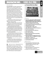
Architect' and Engineer's Specifications 1. GENERAL CONFIGURATION. The mixer shall accommodate 4 microphone signals: mono channels 1-4; 12 line signals: mono channels 1-4 and stereo channels 5-12; 2 stereo pairs of Aux Return inputs; 4 Send/Return channel Inserts; 2 stereo pairs of Main Mix outputs; 1 stereo pair of RCA-type Tape Inputs; 1 stereo pair of RCA-type Tape Outputs; 1 stereo pair of Control Room outputs; 1 stereo pair of Alt 3-4 outputs; 2 Aux Send outputs; and 1 stereo headphone output. The mixer shall be capable of placement on a table or installation in a standard 19-inch rack mount (using optional rack rail brackets) and shall be entirely self-contained. 2. MIXER INPUTS. MONO CHANNELS 1-4: The mixer shall include 4 XDR electronically balanced mic inputs, using XLR3-F-type connectors, accepting nominal levels from -60dBu to +4dBu via 4 rotary Trim controls. 48V phantom power shall be available via a globally-controlled rocker-type switch. 4 balanced or unbalanced line inputs shall be wired in parallel, using 1/4" TRS phone jacks, accepting nominal levels from -45dBu to +4dBu. The mixer shall include 4 channel Inserts using 1/4" TRS phone jacks (tip=send, ring=return, sleeve=ground), delivering and accepting nominal levels from -10dBV to +4dBu. STEREO CHANNELS 5/6, 7/8, 9/10 and 11/12: The mixer shall include 8 bal/unbal line inputs, forming 4 stereo input pairs, using 1/4" TRS phone jacks and accepting nominal levels from -10dBV to +4dBu. OTHER INPUTS: The mixer shall include 4 bal/unbal Aux Return inputs, forming two stereo pairs, using 1/4" TRS phone jacks and accepting nominal levels from -10dBV to +4dBu. The mixer shall include 1 stereo pair of Tape In jacks, using unbalanced RCAtype phono jacks, accepting nominal levels from -20dBV to +4dBu. 3. MIXER OUTPUTS. MAIN OUTPUTS: The mixer's Main Output stereo pairs shall be fitted in three ways: Using balanced XLR-3-M-type connectors, maximum output of +28dBu, including 1 Main Output Level switch to provide 30dB attenuation (XLR outputs only); using bal/unbal 1/4" TRS phone jacks, delivering nominal levels from -10dBV to +4dBu; and using unbalanced RCA-type phono jacks (labeled TAPE OUT) delivering nominal levels from -10dBV to +4dBu. OTHER OUTPUTS: The mixer shall include 1 stereo pair of Alt 3-4 outputs using bal/unbal 1/4" TRS phone jacks, delivering nominal levels from -10dBV to +4dBu; 1 stereo pair of Control Room outputs using bal/unbal 1/4" TRS phone jacks, delivering nominal levels from -10dBV to +4dBu; 2 Aux Send outputs using bal/unbal 1/4" TRS phone jacks, delivering nominal levels from -10dBV to +4dBu; and 1 stereo Headphones output using an unbalanced 1/4" TRS phone jack (tip=left, ring=right, sleeve=ground). 4. MIXER INPUT SECTION. Each channel shall include 1 rotary Trim control; 1 Low Cut filter (HPF), providing an 18dB per octave curve starting at 75Hz; 2 rotary Aux Send controls, providing up to 15dB above unity gain; 3 rotary equalization (EQ) controls: +15dB @ 12kHz shelving, +12dB @ 2.5kHz peaking and +15dB @ 80kHz shelving; 1 rotary Pan control, 4dB attenuation panned center; 1 Mute/Alt 3-4 switch, to be used as a channel mute or to route the signal to the alternate stereo bus (Alt 3-4); 1 PFL (Pre-Fader Listen solo) switch; and 1 rotary channel Gain control, providing up to 20dB above unity gain. Note: The stereo channels (5/6, 7/8, 9/10 and 11/12) shall not include the Trim or Low Cut controls. 5. MIXER OUTPUT SECTION. The mixer shall have 1 rotary Main Mix control, providing up to 10dB above unity gain; 1 rotary Control Room/Phones control, providing up to 10dB above unity gain; 1 Source Matrix including 3 switches to deliver any combination of stereo signals to the Control Room, Phones and Meters, including Main Mix, Alt 3-4 and Tape, which shall be replaced by any solo signals resulting from the engagement of any channel's PFL switch; 1 Assign to Main Mix switch to deliver the Source Matrix signals to the Main Mix; 2 rotary Aux Return level controls, providing up to 20dB above unity gain; 1 rotary Aux Send 1 Master control, providing up to 10dB above unity gain; 1 Aux Send 1 global Pre/Post switch; 1 EFX to Monitor switch, allowing Aux Return 1 signals to be delivered to Aux Send 1 via the Aux Return 2 level control; and 1 blinking red Solo LED, to indicate a solo condition. 6. METERING. The mixer shall include 1 stereo 12-segment LED meter with points at -30, -20, -10, -7, -4, -2, 0, +2, +4, +7, +10 and 28dB (clip). The source signals for the meters shall be the same signals selected in the Source Matrix, and a solo condition shall replace the Source selection with the soloed channel(s). The meters shall be calibrated so that a 0dBu signal at the Control Room output shall be indicated as 0dB on the meters, ±1dB.
-
 1
1 -
 2
2 -
 3
3 -
 4
4 -
 5
5 -
 6
6
 |
 |
