Mackie HM54 Owner's Manual - Page 9
Rear Panel
 |
View all Mackie HM54 manuals
Add to My Manuals
Save this manual to your list of manuals |
Page 9 highlights
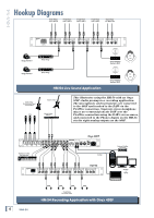
Owner's Manual Rear Panel 9. LEFT and RIGHT MAIN INPUT The rear panel is where you make all your analog audio connections to the HM-54 (except for the convenient additional headphone jacks on the front). 6. IEC Power Receptacle This is a standard 3-prong IEC power connector. Connect the detachable linecord (included in the box with your HM-54) to the power receptacle, and plug the other end of the linecord into an AC outlet properly configured for your particular model. 7. LEFT and RIGHT PHONES INPUT These 1/4" TRS jacks accept a balanced or unbalanced line-level input signal. This is the signal that you select when you push in the SOURCE select switch [3] on the front panel, so connect the individual headphone mix from the mixer to these inputs. The 1/4" TRS inputs are wired as follows: Sleeve = Shield or ground Tip = Positive (+ or hot) Ring = Negative (- or cold) If you are connecting a mono input signal to these inputs, use a Y-Cord splitter to connect the signal to both inputs (otherwise you will only hear the signal in one side of the headphones). See "Mults and Y's" in Appendix B for more info. These 1/4" TRS jacks accept a balanced or unbalanced line-level input signal. This is the signal that you select when you leave the SOURCE select switch [3] on the front panel in the out position, so connect the main mix output from the mixer to these inputs. The 1/4" TRS inputs are wired as follows: Sleeve = Shield or ground Tip = Positive (+ or hot) Ring = Negative (- or cold) If you are connecting a mono input signal to these inputs, use a Y-Cord splitter to connect the signal to both inputs (otherwise you will only hear the effects in one side of the headphones). See "Mults and Y's" in Appendix B for more info. 10. MAIN PHONES INPUT This is a 1/4" TRS headphone input jack. This allows you to use the headphone output from your mixer to provide the main mix signal to the HM-54. Simply use a TRS-to-TRS cable to connect the PHONES output from the mixer to this input on the HM-54. Note: Plugging the main mix signal into the MAIN PHONES INPUT jack automatically disconnects the LEFT and RIGHT MAIN INPUT [9] jacks. 8. PHONES OUTPUT This is another headphone output that duplicates the PHONES [2] output on the front panel. Typically, you would use these when installing the HM-54 in a rack and hard-wiring the headphone outputs to a patch panel in the rack. Note: Plugging headphones into the front panel PHONES jack automatically disconnects the signal from the rear panel PHONES jack. HM-54 ~120VAC 50/60 HZ 12W .25A/250V PHONES INPUT LEFT RIGHT 4 OUTPUT PHONES PHONES INPUT LEFT RIGHT 3 OUTPUT PHONES PHONES INPUT LEFT RIGHT 2 OUTPUT PHONES PHONES INPUT LEFT RIGHT 1 OUTPUT PHONES MAIN LINE INPUT LEFT RIGHT PHONES INPUT Owner's Manual 9
-
 1
1 -
2
-
3
-
 4
4 -
 5
5 -
 6
6 -
 7
7 -
 8
8 -
 9
9 -
 10
10 -
 11
11 -
 12
12 -
 13
13 -
 14
14 -
15
-
16
 |
 |
