Makita BO3710 Owners Manual - Page 4
Save These Instructions., Symbols, Functional Description, Assembly - manual
 |
View all Makita BO3710 manuals
Add to My Manuals
Save this manual to your list of manuals |
Page 4 highlights
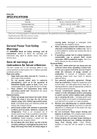
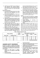
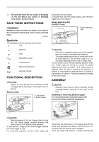
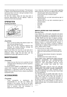
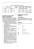
8. Be sure that there are no cracks or breakage on the pad before use. Cracks or breakage may cause a personal injury. SAVE THESE INSTRUCTIONS. WARNING: MISUSE or failure to follow the safety rules stated in this instruction manual may cause serious personal injury. USD205-1 Symbols The followings show the symbols used for tool. ・ volts ・ amperes ・ hertz ・ alternating current ・ no load speed ・ Class II Construction ・ orbits per minute FUNCTIONAL DESCRIPTION CAUTION: • Always be sure that the tool is switched off and unplugged before adjusting or checking function on the tool. Switch action 1. Lock button 2. Switch trigger 1 2 then push in the lock button. To stop the tool from the locked position, pull the switch trigger fully, then release it. Speed adjusting dial For BO3711 only 1. Speed adjusting 1 dial 010226 CAUTION: • If the tool is operated continuously at low speeds, the motor will get overloaded and heated up. • The speed adjusting dial can be turned only as far as 5 and back to 1. Do not force it past 5 or 1, or the speed adjusting function may no longer work. The tool speed can be infinitely adjusted between 4,000 and 11,000 orbits per minute by turning the speed adjusting dial, which is marked 1 to 5. Higher speed is obtained when the dial is turned in the direction of number 5, lower speed is obtained when it is turned in the direction of number 1. Adjust the desired tool speed for the kind of work. ASSEMBLY CAUTION: • Always be sure that the tool is switched off and unplugged before carrying out any work on the tool. Installing or removing abrasive paper For conventional type of abrasive paper with pre-punched holes (standard equipment): 010214 2 2 1 1 CAUTION: • Before plugging in the tool, always check to see that the switch trigger actuates properly and returns to the "OFF" position when released. To start the tool, simply pull the switch trigger. Release the switch trigger to stop. For continuous operation, pull the switch trigger and 010216 Press down the clamp lever (1 in the figure) and with the clamp lever pressed down slide it toward the tool (2 in the figure) and the clamper will be released. Insert the paper end between a clamper and the pad 4
-
 1
1 -
 2
2 -
 3
3 -
 4
4 -
 5
5 -
 6
6 -
 7
7 -
 8
8 -
 9
9 -
 10
10 -
11
-
12
-
13
-
14
-
15
-
16
-
17
-
18
-
19
-
20
 |
 |
