Makita DS4011 Owners Manual - Page 4
Save These Instructions., Symbols, Functional Description, Assembly, Operation - manual
 |
View all Makita DS4011 manuals
Add to My Manuals
Save this manual to your list of manuals |
Page 4 highlights
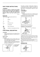
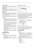
SAVE THESE INSTRUCTIONS. WARNING: DO NOT let comfort or familiarity with product (gained from repeated use) replace strict adherence to safety rules for the subject product. MISUSE or failure to follow the safety rules stated in this instruction manual may cause serious personal injury. USD201-2 Symbols The followings show the symbols used for tool. ・ volts ・ amperes ・ hertz ・ alternating current ・ no load speed ・ Class II Construction ・ revolutions or reciprocation per minute The switch is reversible, providing either clockwise or counterclockwise rotation. To start the tool, simply pull the lower part of the switch trigger for clockwise or the upper part for counterclockwise. Release the switch trigger to stop. ASSEMBLY CAUTION: • Always be sure that the tool is switched off and unplugged before carrying out any work on the tool. Installing top grip (auxiliary handle) 011311 Screw the top grip on the tool securely. Installing or removing drill bit 1. Drill chuck FUNCTIONAL DESCRIPTION CAUTION: • Always be sure that the tool is switched off and unplugged before adjusting or checking function on the tool. Switch action CAUTION: • Before plugging in the tool, always check to see that the switch trigger actuates properly and returns to the "OFF" position when released. • Change the direction of rotation only when the tool comes to a complete stop. Changing it before the tool stops may damage the tool. 1 2 3 1. Counterclockwise 2. Switch trigger 3. Clockwise 1 011313 To install the bit, place it in the chuck as far as it will go. Tighten the chuck by hand. Place the chuck key in each of the three holes and tighten clockwise. Be sure to tighten all three chuck holes evenly. To remove the bit, turn the chuck key counterclockwise in just one hole, then loosen the chuck by hand. After using the chuck key, be sure to return to the original position. OPERATION 011310 011314 4
-
 1
1 -
 2
2 -
 3
3 -
 4
4 -
 5
5 -
 6
6 -
 7
7 -
 8
8 -
 9
9 -
 10
10 -
11
-
12
-
13
-
14
-
15
-
16
-
17
-
18
-
19
-
20
 |
 |
