Makita GA4534 Owners Manual - Page 6
Save These Instructions., Symbols, Functional Description - manual
 |
View all Makita GA4534 manuals
Add to My Manuals
Save this manual to your list of manuals |
Page 6 highlights
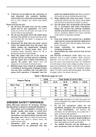
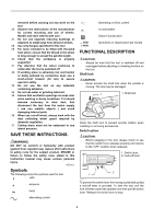
removed before carrying out any work on the tool. 26. Observe the instructions of the manufacturer for correct mounting and use of wheels. Handle and store wheels with care. 27. Do not use separate reducing bushings or adaptors to adapt large hole abrasive wheels. 28. Use only flanges specified for this tool. 29. For tools intended to be fitted with threaded hole wheel, ensure that the thread in the wheel is long enough to accept the spindle length. 30. Check that the workpiece is properly supported. 31. Pay attention that the wheel continues to rotate after the tool is switched off. 32. If working place is extremely hot and humid, or badly polluted by conductive dust, use a short-circuit breaker (30 mA) to assure operator safety. 33. Do not use the tool on any materials containing asbestos. 34. Do not use water or grinding lubricant. 35. Ensure that ventilation openings are kept clear when working in dusty conditions. If it should become necessary to clear dust, first disconnect the tool from the mains supply ( use non metallic objects ) and avoid damaging internal parts. 36. When use cut-off wheel, always work with the dust collecting wheel guard required by domestic regulation. 37. Cutting discs must not be subjected to any lateral pressure. SAVE THESE INSTRUCTIONS. WARNING: DO NOT let comfort or familiarity with product (gained from repeated use) replace strict adherence to safety rules for the subject product. MISUSE or failure to follow the safety rules stated in this instruction manual may cause serious personal injury. USD292-2 Symbols The followings show the symbols used for tool. ・ volts ・ amperes ・ hertz ・ alternating current ・ alternating or direct current ・ no load speed ・ Class II Construction ・ revolutions or reciprocation per minute FUNCTIONAL DESCRIPTION CAUTION: • Always be sure that the tool is switched off and unplugged before adjusting or checking function on the tool. Shaft lock CAUTION: • Never actuate the shaft lock when the spindle is moving. The tool may be damaged. 1 1. Shaft lock 010690 Press the shaft lock to prevent spindle rotation when installing or removing accessories. Switch action CAUTION: • Before plugging in the tool, always check to see that the switch lever actuates properly and returns to the "OFF" position when released. 1. Switch lever 2. Lock-off lever 2 1 010691 To prevent the switch lever from being accidentally pulled, a lock-off lever is provided. To start the tool, pull the lock-off lever toward the operator and then pull the switch lever. Release the switch lever to stop. 6
-
 1
1 -
 2
2 -
 3
3 -
 4
4 -
 5
5 -
 6
6 -
 7
7 -
 8
8 -
 9
9 -
 10
10 -
 11
11 -
 12
12 -
13
-
14
-
15
-
16
-
17
-
18
-
19
-
20
-
21
-
22
-
23
-
24
-
25
-
26
-
27
-
28
-
29
-
30
-
31
-
32
-
33
-
34
-
35
-
36
-
37
-
38
-
39
-
40
 |
 |
