Makita LS1016 Technical Reference - Page 16
] DISASSEMBLY/ASSEMBLY, 3]-4. Safety cover A, epair
 |
View all Makita LS1016 manuals
Add to My Manuals
Save this manual to your list of manuals |
Page 16 highlights
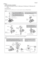
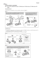
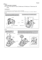
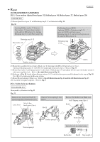
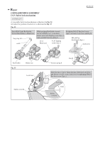
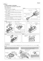
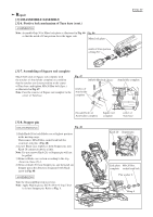
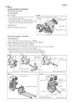
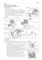
Repair [3] DISASSEMBLY/ASSEMBLY [3]-4. Safety cover A P 16/ 37 ASSEMBLING (1) Assemble Safety cover A section as illustrated in Fig. 34. And then mount the Safety cover A section to Safety cover B as illustrated in Fig. 35. (2) Mount the Safety cover section to Blade case complete as illustrated in Fig. 36. Fig. 34 After applying grease to Torsion spring 45, set the tails to Safety cover A as illustrated below. Torsion spring 45 Boss (5points) Put Center washer on the Torsion spring 45, fitting its five holes to the five bosses of Safety cover A. After mounting Center cover, assemble Center plate, fitting its five holes to five bosses of Safety cover A . Center plate Center washer Safety cover A Apply Grease to this portion which contacts the hole of Center cover . Fig. 35 Mount the Safety cover A section to the Safety cover B by tightening with 4x12 Tapping screw (3pcs.). Center cover 4x12 Tapping Screw (3pcs.) Center cover Safety cover A Safety cover B Fig. 36 Tighten Center cover with Hex flange head bolt M8x12. But reserve the allowance to move the Center cover. Move Center cover until its protrusion touches the flange of M8x12 Hex flange head bolt. Tighten Center cover with Hex flange head bolt firmly.
-
 1
1 -
2
-
3
-
4
-
5
-
6
-
7
-
8
-
9
-
10
-
 11
11 -
 12
12 -
 13
13 -
 14
14 -
 15
15 -
 16
16 -
 17
17 -
 18
18 -
 19
19 -
 20
20 -
 21
21 -
22
-
23
-
24
-
25
-
26
-
27
-
28
-
29
-
30
-
31
-
32
-
33
-
34
-
35
-
36
-
37
 |
 |
