Makita LS1016 Technical Reference - Page 6
] DISASSEMBLY/ASSEMBLY, 3]-1. Blade case, Motor epair
 |
View all Makita LS1016 manuals
Add to My Manuals
Save this manual to your list of manuals |
Page 6 highlights
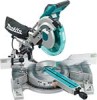
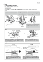
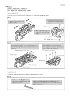
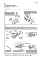
Repair [3] DISASSEMBLY/ASSEMBLY [3]-1. Blade case, Motor section DISASSEMBLING Fig. 7 Note: Refer to Fig. 7. The three notches on Blade case have important role for disassembly / assembly. (1) Disconnect the linkage of Blade case with Arm and Base section by removing Strain relief and Link plate as illustrated in Figs. 8 and 9. Fig. 8 Blade case P 6/ 37 notch A: locking Blade case to Base at 90 degrees notch B: locking Blade case at starting position notch C: locking Blade case at the lowest position Aligning notch B with Stopper pin, push Knob 20 toward the notch. Blade case can be locked at starting position. Blade case Remove Strain reliefs from Arm complete and Blade case by unscrewing 4x12 Tapping screw (2pcs.). Strain relief notch B 4x12 Tapping screw Knob 20 4x12 Tapping screw Strain relief Remove M4x10 Pan head screw (2pcs.) for Guard as illustrated below and then separate Guard section. Guard section M4x10 Pan head screw (2pcs.) Fig. 9 Remove Link plate as illustrated below. 1. Remove Stop ring E-5, Flat washer 6 and Ring 6. Link plate complete can be free from blade case. Stop ring E-5 Flat washer 6 Ring 6 Link plate complete 2. Remove M6x20 Hex socket head bolt, Flat washer 6 and Ring 6. Link plate complete can be free from Front arm. M6x20 Hex socket head bolt Flat washer 6 Ring 6
-
 1
1 -
 2
2 -
 3
3 -
 4
4 -
 5
5 -
 6
6 -
 7
7 -
 8
8 -
 9
9 -
 10
10 -
 11
11 -
 12
12 -
13
-
14
-
15
-
16
-
17
-
18
-
19
-
20
-
21
-
22
-
23
-
24
-
25
-
26
-
27
-
28
-
29
-
30
-
31
-
32
-
33
-
34
-
35
-
36
-
37
 |
 |