Marantz NR1604 Owner's Manual in English - Page 143
Rear panel, Digital audio connectors DIGITAL AUDIO
 |
View all Marantz NR1604 manuals
Add to My Manuals
Save this manual to your list of manuals |
Page 143 highlights
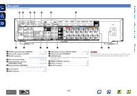
Basic instructions Rear panel See the page indicated in parentheses ( ). Q4 Q3 Q2 Q1 Q0 o i Advanced instructions Information q w e r t y u q FM/AM antenna terminals (ANTENNA 18) w Analog audio connectors (AUDIO 14, 15, 17) e PRE OUT connectors 83, 84, 85, 86, 87, 88, 89, 90) r Video connectors (VIDEO 13, 14, 15) t Component video connectors (COMPONENT VIDEO 13, 14, 15) y Speaker terminals (SPEAKERS) 83, 84, 85, 86, 87, 88, 89, 90, 101) u AC inlet (AC IN 21) i HDMI connectors 9, 10) o Digital audio connectors (DIGITAL AUDIO 13, 14) Q0 Network connector (NETWORK 20) Q1 FLASHER IN jack Used when using a control BOX or other such control devices to control this unit. Q2 REMOTE CONTROL connectors 93) Q3 M-XPort connector 19) Q4 DC OUT connector 94) NOTE Do not touch the inner pins of the connectors on the rear panel. Electrostatic discharge may cause permanent damage to the unit. 140 DVD
-
 1
1 -
2
-
3
-
4
-
5
-
6
-
7
-
8
-
9
-
10
-
11
-
12
-
13
-
14
-
15
-
16
-
17
-
18
-
19
-
20
-
21
-
22
-
23
-
24
-
25
-
26
-
27
-
28
-
29
-
30
-
31
-
32
-
33
-
34
-
35
-
36
-
37
-
38
-
39
-
40
-
41
-
42
-
43
-
44
-
45
-
46
-
47
-
48
-
49
-
50
-
51
-
52
-
53
-
54
-
55
-
56
-
57
-
58
-
59
-
60
-
61
-
62
-
63
-
64
-
65
-
66
-
67
-
68
-
69
-
70
-
71
-
72
-
73
-
74
-
75
-
76
-
77
-
78
-
79
-
80
-
81
-
82
-
83
-
84
-
85
-
86
-
87
-
88
-
89
-
90
-
91
-
92
-
93
-
94
-
95
-
96
-
97
-
98
-
99
-
100
-
101
-
102
-
103
-
104
-
105
-
106
-
107
-
108
-
109
-
110
-
111
-
112
-
113
-
114
-
115
-
116
-
117
-
118
-
119
-
120
-
121
-
122
-
123
-
124
-
125
-
126
-
127
-
128
-
129
-
130
-
131
-
132
-
133
-
134
-
135
-
136
-
137
-
 138
138 -
 139
139 -
 140
140 -
 141
141 -
 142
142 -
 143
143 -
 144
144 -
 145
145 -
 146
146 -
 147
147 -
 148
148 -
149
-
150
-
151
-
152
-
153
-
154
-
155
-
156
-
157
-
158
-
159
-
160
-
161
-
162
-
163
-
164
-
165
-
166
-
167
-
168
 |
 |
