Maytag MEDB700BW Installation Guide - Page 6
Install Leveling Legs - dryer
 |
View all Maytag MEDB700BW manuals
Add to My Manuals
Save this manual to your list of manuals |
Page 6 highlights
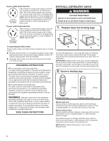
If your outlet looks like this: 4-wire receptacle (14-30R) Then choose a 4-wire power supply cord with ring or spade terminals and UL listed strain relief. The 4-wire power supply cord, at least 4 ft. (1.22 m) long, must have 4 10-gauge solid copper wires and match a 4-wire receptacle of NEMA Type 14-30 R. The ground wire (ground conductor) may be either green or bare. The neutral conductor must be identified by a white cover. If your outlet looks like this: 3-wire receptacle (10-30R) Then choose a 3-wire power supply cord with ring or spade terminals and UL listed strain relief. The 3-wire power supply cord, at least 4 ft. (1.22 m) long, must have 3 10-gauge solid copper wires and match a 3-wire receptacle of NEMA Type 10-30R. INSTALL LEVELING LEGS 1. Prepare dryer for leveling legs If connecting by direct wire: Power supply cable must match power supply (4-wire or 3-wire) and be: ■■ Flexible armored cable or nonmetallic sheathed copper cable (with ground wire), covered with flexible metallic conduit. All current-carrying wires must be insulated. ■■ 10-gauge solid copper wire (do not use aluminum) at least 5 ft. (1.52 m) long. To avoid damaging floor, use a large flat piece of cardboard from dryer carton; place under entire dryer. Firmly grasp dryer body (not console panel) and gently lay dryer down on cardboard. IMPORTANT: If laying dryer on its back, use the cardboard corner posts the dryer was packed with to avoid damaging the back of the dryer. Lay the dryer on its side if you do not have the cardboard corner posts the dryer was packed with. 2. Screw in leveling legs Flange Flange Models with riser Models without riser Models with riser: Using a wrench, screw legs into cabinet until foot flange touches the riser. Foot is fully installed when bottom of foot is approximately 1/2" (13 mm) from bottom of the riser. Models without riser: Using a wrench and tape measure, screw legs into leg holes until bottom of foot is approximately 13/8" (35 mm) from bottom of dryer. Now stand the dryer on its legs. Slide the dryer until it is close to its final location. Leave enough room for electrical connection and to connect the exhaust vent. NOTE: Refer to Dryer Dimensions in the Location Requirements. 6
-
 1
1 -
 2
2 -
 3
3 -
 4
4 -
 5
5 -
 6
6 -
 7
7 -
 8
8 -
 9
9 -
 10
10 -
 11
11 -
 12
12 -
13
-
14
-
15
-
16
-
17
-
18
-
19
-
20
 |
 |
