Maytag MGDB850WB Use and Care Guide - Page 5
Installation Instructions - parts
 |
UPC - 883049179339
View all Maytag MGDB850WB manuals
Add to My Manuals
Save this manual to your list of manuals |
Page 5 highlights
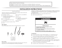
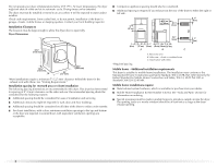
INSTALLATION INSTRUCTIONS Tools and Parts Gather the required tools and parts before starting installation. Read and follow the instructions provided with any tools listed here. ■ Flat-blade screwdriver ■ Tin snips (new vent installation) ■ Adjustable wrench that opens to ■ Level 1" (25 mm) or hex-head socket wrench (for adjusting dryer feet) ■ Vent clamps ■ 8" or 10" pipe wrench ■ Caulking gun and compound (for installing new exhaust vent) ■ 8" or 10" adjustable wrench (for gas connections) ■ Tape measure ■ Pipe-joint compound resistant to LP gas ■ Knife Mobile home installations require metal exhaust system hardware available for purchase from the dealer from whom you purchased your dryer. For information on ordering, please refer to the "Assistance or Service" section. You may also contact the dealer from whom you purchased your dryer. ■ Mobile home installation kit. Ask for Part Number 346764. ■ Metal exhaust system hardware. Location Requirements ■ Pliers Parts supplied: Remove parts package from dryer drum. Check that all parts were included. A B C D E A. Leveling legs (4) B. "Y" connector C. Short inlet hose D. Long inlet hose E. Rubber washer Parts needed: Check local codes. Check existing electrical supply and venting and see "Electrical Requirements" and "Venting Requirements" before purchasing parts. You will need ■ A location that allows for proper exhaust installation. See "Venting Requirements." ■ If you are using a power supply cord, a grounded electrical outlet located within 2 ft (610 mm) of either side of the dryer. See "Electrical Requirements." ■ A sturdy floor to support the total weight (dryer and load) of 200 lbs (90.7 kg). The combined weight of a companion appliance should also be considered. ■ Cold water faucets located within 4 ft (1.2 m) of the water fill valves, and water pressure of 20-100 psi (138-690 kPa). You may use the water supply for your washer using the "Y" connector and short hose (if needed) which are provided. ■ 20-100 psi (138-690 kPa) for best performance. ■ A level floor with a maximum slope of 1" (25 mm) under entire dryer. 5
-
 1
1 -
 2
2 -
 3
3 -
 4
4 -
 5
5 -
 6
6 -
 7
7 -
 8
8 -
 9
9 -
 10
10 -
 11
11 -
12
-
13
-
14
-
15
-
16
-
17
-
18
-
19
-
20
-
21
-
22
-
23
-
24
-
25
-
26
-
27
-
28
-
29
-
30
-
31
-
32
-
33
-
34
-
35
-
36
-
37
-
38
-
39
-
40
-
41
-
42
-
43
-
44
-
45
-
46
-
47
-
48
-
49
-
50
-
51
-
52
-
53
-
54
-
55
-
56
-
57
-
58
-
59
-
60
 |
 |
