Maytag MMV1175J Installation Instructions - Page 8
Drill Holes in Rear Wall, Attach Mounting Plate to Wall
 |
View all Maytag MMV1175J manuals
Add to My Manuals
Save this manual to your list of manuals |
Page 8 highlights
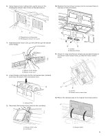
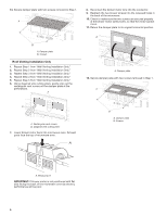
3. Holding the cardboard template in place, mark both holes in the lower corners and draw a horizontal line across the bottom edge of the cardboard template. These represent the mounting plate's end holes and bottom edge. 4. Remove the cardboard template and check the markings: Upper cabinet bottom 15⁵⁄₈" (39.71 cm) Centerline 17¹⁄₃ " (44.02 cm) 14¹⁄₈" (35.96 cm) 14¹⁄₈" (35.96 cm) Mounting plate end hole Bottom of mounting plate ■ The bottom edge line must be 171⁄3" (44.02 cm) from the bottom of the upper cabinet and must be level. ■ The end holes must be 155⁄8" ( 39.71 cm) from the bottom edge of the upper cabinet and must be on a level line with each other. They must each be 141⁄8" (35.96 cm) from the centerline. 5. With the support tabs facing forward (see illustrations in the "Locate Wall Stud(s)" section), align the mounting plate center markers to the centerline on the wall, making sure its bottom edge is aligned to the horizontal line drawn in Step 3 and that the end holes are properly marked. Make sure the mounting plate is level. 6. Holding the mounting plate in place, find the wall stud centerline(s) drawn in Step 2 of "Locate Wall Stud(s)" and mark at least one, preferably two hole(s) through the mounting plate, closest to the wall stud centerline(s). See figures 1, 2, and/or 3 in "Possible Wall Stud Configurations" in the "Locate Wall Stud(s)" section. The blackened holes in the shaded areas are ideal hole locations. 7. Set the mounting plate aside. Wall Venting Installation Only Upper cabinet bottom 3/8" (1 cm) 4" (10.2 cm) Centerline 6" (15.2 cm) 6" (15.2 cm) 8. Mark the centerline 3/8" (1 cm) down from the bottom edge of the upper cabinet. 9. Using measuring tape, measure out 6" (15.2 cm) on both sides of the centerline, and mark. 10. Measure down 4" (10.2 cm) from the mark made in Step 8 and mark. 11. Using a straightedge, draw the two horizontal, level lines through the marks made in steps 8 and 10. 12. Draw the two vertical plumb lines down from the marks made in Step 9 to complete the 12" x 4" (30.5 x 10.2 cm) rectangle. This is the venting cutout area. 13. Cut a 3/4" (1.9 cm) hole in one corner of the cutout area. 14. Using a keyhole saw, cut out the venting cutout area. Drill Holes in Rear Wall In addition to being installed on at least one wall stud, the mounting plate must attach to the wall at both end holes. If the end holes are not over wall studs, use two 3/16-24 x 3" round head bolts with toggle nuts; if one end hole is over a wall stud, use one lag screw and one 3/16-24 x 3" round-head bolt with toggle nut; or if both end holes are over wall studs, use two lag screws. Following are three installation configurations. Installation for No Wall Studs at End Holes (Figures 1 and 2) 1. Drill 5/8" (1.6 cm) holes through the wall at both end holes marked in Step 3 of the "Mark Rear Wall." 2. Drill 3/16" (5 mm) hole(s) into the wall stud(s) at the hole(s) marked in Step 6 of the "Mark Rear Wall." Refer to figures 1 and 2 in "Possible Wall Stud Configurations" in the"Locate Wall Stud(s)" section. Installation for Wall Stud at One End Hole (Figure 3) 1. Drill a 3/16" (5 mm) hole into the wall stud at the end hole marked in Step 3 of the "Mark Rear Wall." 2. If installing on a second wall stud, drill a 3/16" (5 mm) hole into the wall stud at the other hole marked in Step 6 of the"Mark Rear Wall." Refer to Figure 3 in "Possible Wall Stud Configurations" in the "Locate all Stud(s)" section. 3. Drill a 5/8" (1.6 cm) hole through the wall at the other end hole. Installation for Wall Studs at Both End Holes (Figure 4) 1. Drill 3/16" (5 mm) holes into the studs at the end holes marked in Step 3 of the "Mark Rear Wall." Attach Mounting Plate to Wall NOTE: Secure the mounting plate to the wall at both end holes drilled into the wall studs and/or drywall using either 3/16-24 x 3" round-head bolts and toggle nuts or 1/4 x 2" lag screws. Refer to illustrations in "Possible Wall Stud Configurations" in the "Locate Wall Stud(s)" section. No Wall Studs at End Holes (Figures 1 and 2) NOTE: The mounting plate must be secured to the wall on at least 1 wall stud as well as at both ends. 1. With the support tabs of the mounting plate facing forward, insert 3/16-24 x 3" round-head bolts through both end holes of mounting plate. 2. Start toggle nuts on bolts from the back of the mounting plate. Leave enough space for the toggle nuts to go through the wall and to open. B A C A. 3/16-24 x 3" round-head bolt B. Mounting plate C. Spring toggle nut 3. Position mounting plate on the wall. 8
-
 1
1 -
2
-
 3
3 -
 4
4 -
 5
5 -
 6
6 -
 7
7 -
 8
8 -
 9
9 -
 10
10 -
 11
11 -
 12
12 -
 13
13 -
14
-
15
-
16
 |
 |
