Maytag MMV4203DB Installation Instructions
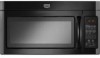
Maytag MMV4203DB - 2.0 cu. Ft. Combination Range Hood-Microwave Manual
 |
UPC - 883049158532
View all Maytag MMV4203DB manuals
Add to My Manuals
Save this manual to your list of manuals |
Maytag MMV4203DB manual content summary:
- Maytag MMV4203DB | Installation Instructions - Page 1
the Microwave Oven 8. Complete Installation 9.. VENTING DESIGN SPECIFICATIONS 10 ASSISTANCE 1..1 Replacement Parts 1.1 Accessories 1..1 MICROWAVE HOOD COMBINATION SAFETY Your safety and the safety of others are very important. We have provided many important safety messages in this manual and - Maytag MMV4203DB | Installation Instructions - Page 2
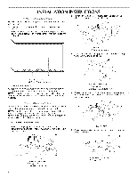
: Upper cabinet template Mounting plate (attached to back of microwave oven) Aluminum grease filters Charcoal filters (Depending on model, charcoal filters may not be included. See User Instructions.) NOTE: Depending on model, aluminum grease filter and charcoal filter may be combined. Materials - Maytag MMV4203DB | Installation Instructions - Page 3
electrician or serviceman if the grounding instructions are not completely understood, or if doubt exists as to whether the microwave oven is properly grounded. Do not use an extension cord. If the power supply cord is too short, have a qualified electrician or serviceman install an outlet near the - Maytag MMV4203DB | Installation Instructions - Page 4
the 2 screws that attach the mounting plate to the back of the microwave oven, then remove mounting plate and set aside. , \ INSTRUCTIONS 2. Remove the blower motor screw from the back of the microwave oven, then lift out blower motor. 6 A. Blower motor B. Blower motor screw 3. Using diagonal - Maytag MMV4203DB | Installation Instructions - Page 5
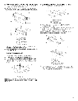
Step 2 from "Wall Venting Installation Only." 3. Rotate blower motor so that exhaust ports face the top of microwave oven, and flat sides of blower motor face back of microwave oven. Lower blower motor back into microwave oven. C D I k J_ _,_ *z\ . A. Guides B. Locking tabs C. Damper assembly - Maytag MMV4203DB | Installation Instructions - Page 6
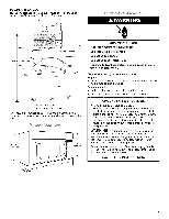
Configurations." Ma_'< Rea_' The microwave oven must be installed on a minimum of 1 Cabinet opening vertical centerllne B. Holes for toggle bolts C. Wall stud centerlines D. Holes for lag screws E. Support tabs F. Mounting plate center marker The top edge line must be 141/2'' (36.8 cm) from the - Maytag MMV4203DB | Installation Instructions - Page 7
a keyhole saw, cut out the venting cutout area. In addition to being installed on at least 1 wall stud, the mounting plate must attach to the lag screws. Refer to illustrations in "Locate Wall Stud(s)" section. 1. With the support tabs of the mounting plate facing forward, insert 3/16-20 x 3" hex- - Maytag MMV4203DB | Installation Instructions - Page 8
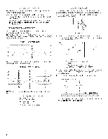
cabinet is metal, the supply cord bushing needs to be installed around the supply cord hole, as shown. 3. Using 2 or more people, lift microwave oven and hang it on support tabs at the bottom of mounting plate. NOTE: To avoid damage to the microwave oven, do not grip or use the door or door handle - Maytag MMV4203DB | Installation Instructions - Page 9
vent fan. 5. If the microwave oven does not operate: • Check problem continues, call an electrician. • Check that the power supply cord is plugged into a grounded 3 prong outlet. • See the User Instructions for troubleshooting information. Installation is now complete. Save Installation Instructions - Maytag MMV4203DB | Installation Instructions - Page 10
SPECIFICATIONS This section is intended for architectural designer and builder/contractor reference only. NOTES: • Vent materials needed for installation are not provided with microwave ) clearance must exist between the top of the microwave oven and the rectangular to round transition piece so that - Maytag MMV4203DB | Installation Instructions - Page 11
in the User Instructions. If any of the installation hardware needs to be replaced, call us at our toll free number listed in the User Instructions. Following is a list of available replacement parts. You will need your model number located on the front facing of the microwave oven opening, behind - Maytag MMV4203DB | Installation Instructions - Page 12
W10188238A SP PN W10188947A © 2008. All rights reserved. DE68-03534A 9/08 Printed in Malaysia
-
 1
1 -
 2
2 -
 3
3 -
 4
4 -
 5
5 -
 6
6 -
 7
7 -
8
-
9
-
10
-
11
-
12
 |
 |
MICROWAVE
HOOD
COMBINATION
INSTALLATION
INSTRUCTIONS
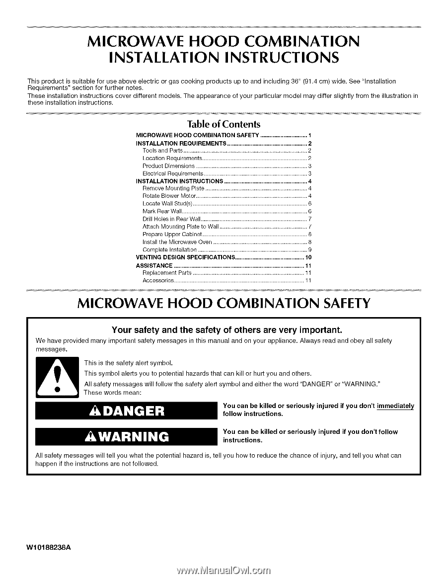
This product
is suitable for use above electric or gas cooking
products
up to and including
36" (91.4 cm) wide. See "Installation
Requirements"
section for further
notes.
These installation
instructions
cover different
models.
The appearance
of your particular
model
may differ slightly from the illustration
in
these installation
instructions.
Table of Contents
MICROWAVE HOOD COMBINATION SAFETY
..............................
1
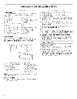
INSTALLATION REQUIREMENTS
...................................................
2
Tools and Parts
...............................................................................
2
Location Requirements
...................................................................
2
Product Dimensions
.......................................................................
3
Electrical Requirements
..................................................................
3
INSTALLATION INSTRUCTIONS
.....................................................
4
Remove Mounting Plate
.................................................................
4
Rotate Blower Motor
.......................................................................
4
Locate Wall Stud(s)
.........................................................................
6
Mark RearWall
................................................................................
6
Drill Holes in RearWall
....................................................................
7
Attach Mounting Plate to Wall
........................................................
7
Prepare Upper Cabinet
...................................................................
8
Install the Microwave Oven
............................................................
8
Complete Installation
......................................................................
9
VENTING DESIGN SPECIFICATIONS
............................................
10
ASSISTANCE
...................................................................................
11
Replacement Parts
.......................................................................
11
Accessories
...................................................................................
11
MICROWAVE
HOOD
COMBINATION
SAFETY
Your safety and the safety of others are very important.
We have provided
many important
safety messages
in this manual and on your appliance.
Always read and obey all safety
messages.
This is the safety alert symbol.
This symbol
alerts you to potential
hazards that can kill or hurt you and others.
All safety
messages
will follow the safety alert symbol and either the word "DANGER"
or "WARNING."
These words mean:
You can be killed or seriously
injured if you don't immediately
follow
instructions.
You can be killed or seriously
injured
if you don't
follow
instructions.
All safety messages
will tell you what the potential
hazard is, tell you how to reduce the chance
of injury, and tell you what can
happen
if the instructions
are not followed.
W10188238A