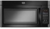
Maytag MMV4203DB Installation Instructions - Page 6

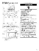
I - One Wall Stud, Two Wall Studs - installation

Page 6 highlights

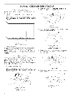
NinOstTatEllhI:fenmowicarollswtuadvoseevxeins.wt ithinthecabineotpeningd,onot Seeillustrationins"PossibWlealSl tudConfigurations." 1. Usingastudfinderl,ocatetheedgesofthewallstud(sw)ithin theopening. 2. MeaacrhksthtuedcceennteteorSrfe.eaecillhustsutrdaa,tniodindnsr"aPwoaspsluibmWleblainlSledtuodwn Configurations." Ma_'< Rea_' The microwave oven must be installed on a minimum of 1 wall stud, preferably 2, using a minimum of 1 lag screw, preferably 2. 1. Using measuring tape, find and clearly mark the vertical centerline of the opening. Possible Wall Stud Configurations These depictions show examples of preferred installation configurations with the mounting plate. NOTE: If wall stud is within 6" (15.2 cm) of the vertical centerline (see "Mark Rear Wall" section), only recirculation or roof venting installation can be done. Figure I - One Wall Stud A. Centerllne 2. Mark the centerline 141/2'' (36.8 cm) down from bottom edge of the upper cabinet (or flush line, if upper cabinet has a hanging front edge - see illustration). A i= c F i_J i D _T _ "J" _ -33 B o. ( o o < o

  • 1
  • 2
  • 3
  • 4
  • 5
  • 6
  • 7
  • 8
  • 9
  • 10
  • 11
  • 12

NOTE:
Ifnowall
studsexist
within
thecabinet
opening,
donot
install
themicrowave
oven.
See
illustrations
in"Possible
Wall
StudConfigurations."
1.Usingastud
finder,
locate
theedgesofthewall
stud(s)
within
theopening.
2. Mark
thecenter
ofeachstud,
anddrawaplumb
linedown
eachstudcenter.
See
illustrations
in"Possible
Wall
Stud
Configurations."
Possible
Wall Stud Configurations
These depictions
show examples
of preferred
installation
configurations
with the mounting
plate.
NOTE: If wall stud is within 6" (15.2 cm) of the vertical centerline
(see "Mark Rear Wall" section), only recirculation
or roof venting
installation
can be done.
Figure I - One Wall Stud
A
i=
c
F
i_J
............
i
_
................
D
_T
_
"J"
_
-33
B
....................................
®
o
(
o
o
<
o
<:
o
_
o
_.
o
o
%,sf
o
:
o
(
o
o
,_
®
..................................
B
(
Q
O_
ooooo_
o o o o o o c_4_
":
o r:o
.F_4_O
[3)
,/
,/
i
i
\
E
i
i
............
;%-
..................
E
i
i
i
i
NOTE: Holes are for installation
with 1 lag screw into the wall stud
and 2 toggle
bolts through
the drywall.
Figure 2 - Two Wall Studs
A
c
.........................................
Lj',
i
I
i
J
i
i
i
i
i
........
C
i
NOTE: Holes are for installation
with 2 lag screws
into the wall
studs.
A. Cabinet
opening
vertical
centerllne
B. Holes
for toggle bolts
C. Wall stud centerlines
D. Holes
for lag screws
E. Support
tabs
F. Mounting
plate center marker
Ma_'<
Rea_'
The microwave
oven must be installed on a minimum
of 1 wall
stud, preferably 2, using a minimum
of 1 lag screw,
preferably 2.
1.
Using measuring
tape, find and clearly mark the vertical
centerline
of the opening.
A. Centerllne
2.
Mark the centerline
141/2
'' (36.8 cm) down from bottom edge of
the upper cabinet (or flush line, if upper cabinet has a hanging
front edge - see illustration).
J
A%%
C
B'
t
141/2,,
(36.8 ore)
A. Rear wall
B. Hanging
front
edge
of upper
cabinet
C. Flush line
D. Mark for top
edge
of mounting
plate
E. Bottom
of smooth
bottom
upper
cabinet
3.
Using a straightedge,
draw a level, horizontal
line through
the
mark made in Step 2. This represents
the top edge of the
mounting
plate.
4.
Remove the mounting
plate and check the markings:
Upper cabinet
bottom
l
i
i
i
i
14W'
CenterJine
{36.8cm)
',
i
i
1
i
The top edge line must be 141/2
'' (36.8 cm) from the bottom
of
the upper cabinet,
and must be level.
6