Maytag MMV4203DB Installation Instructions - Page 7
All<
 |
UPC - 883049158532
View all Maytag MMV4203DB manuals
Add to My Manuals
Save this manual to your list of manuals |
Page 7 highlights
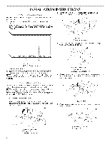
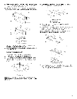
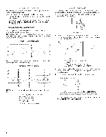
5. With the support tabs facing forward (see illustrations in "Locate Wall Stud(s)" section, align the mounting plate center marker to the centerline on the wall, making sure its top edge is aligned with the horizontal line drawn in Step 3. Make sure the mounting plate is level. 6. Through the mounting plate, mark a hole at each end of the mounting plate. These are the mounting holes. 7. Holding the mounting plate in place, and making sure it is aligned with the top edge line, centerline and the mounting holes, find the wall stud centerline(s) drawn in Step 2 of "Locate Wall Stud(s)." Mark at least 1, preferably 2 hole(s) through the mounting plate, closest to the wall stud centerline(s). See illustrations in "Locate Wall Stud(s)" section. The blackened holes in the shaded areas are ideal hole locations. 8. Set the mounting plate aside. Wall Venting Installation Only Centerline Upper cabinet bottom I t 4" (10.2crn) %" (1 cm) 6" (15.2 crn) 6" (15.2 crn) 9. Mark the centerline 3/8" (1 cm) down from the bottom edge of the upper cabinet. 10. Using measuring tape, measure out 6" (15.2 cm) on both sides of the centerline, and mark. 11. Measure down 4" (10.2 cm) from the mark made in Step 9, and mark. 12. Using a straightedge, draw the 2 horizontal, level lines through the marks made in steps 9 and11. 13. Draw the 2 vertical, plumb lines down from the marks made in Step 7 to complete the 12" x 4" (30.5 x 10.2 cm) rectangle. This is the venting cutout area. 14. Cut a 3/4" (19 mm) hole in one corner of the cutout area. 15. Using a keyhole saw, cut out the venting cutout area. In addition to being installed on at least 1 wall stud, the mounting plate must attach to the wall through mounting holes on both ends. If the mounting holes are not over wall studs, use two 3/1620 x 3" hex-head bolts with toggle nuts. If 1 hole is over a wall stud, use 1 lag screw and one 3/16-20 x 3" hex-head bolt with toggle nut. If both end mounting holes are over wall studs, use 2 lag screws. 1. Drill 5/8" (16 mm) hole(s) through the wall at holes marked for 3/16-20 x 3" hex-head bolt(s) with toggle nut(s). 2. Drill 1/8" (3 mm) hole(s) into the wall stud(s) at the hole(s) marked in Step 7 of "Mark Rear Wall." Refer to illustrations in "Possible Wall Stud Configurations" in "Locate Wall Stud(s)" section. All
-
 1
1 -
 2
2 -
 3
3 -
 4
4 -
 5
5 -
 6
6 -
 7
7 -
 8
8 -
 9
9 -
 10
10 -
 11
11 -
 12
12
 |
 |
