Motorola 2700 User Manual - Page 15
Planning the Powerline MU Network
 |
View all Motorola 2700 manuals
Add to My Manuals
Save this manual to your list of manuals |
Page 15 highlights
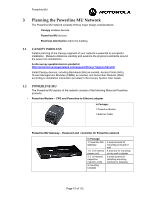
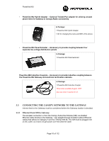
Powerline MU 3 Planning the Powerline MU Network The Powerline MU network consists of three major design considerations: • Canopy wireless devices • Powerline MU devices • Electrical distribution within the building 3.1 CANOPY WIRELESS Careful planning of the Canopy segment of your network is essential to successful installation. Measure distances carefully and examine the physical constraints around the power line installations. A site survey questionnaire is posted at http://motorola.canopywireless.com/support/library/?region=1&cat=8 Install Canopy devices, including Backhauls (BH) as needed, Access Points (APs), Cluster Management Modules (CMMs) as needed, and Subscriber Modules (SMs) according to installation information provided in the Canopy System User Guide. 3.2 • POWERLINE MU The Powerline MU section of the network consists of the following Motorola Powerline products: Powerline Modem - CPE and Powerline-to-Ethernet adapter In Package: 1 Powerline Modem 1 Ethernet Cable Powerline MU Gateway - Head-end and controller for Powerline network In Package: 1 Powerline MU Gateway 1 6' (1.8 meters) power cord 3 3' (.9 meters) capacitive injection cords 2 mounting brackets 8 wood screws for mounting on board or wall 8 anchors for mounting on dry wall or plaster 6 small screws for attaching mounting brackets to Gateway Page 15 of 112
-
 1
1 -
2
-
3
-
4
-
5
-
6
-
7
-
8
-
9
-
 10
10 -
 11
11 -
 12
12 -
 13
13 -
 14
14 -
 15
15 -
 16
16 -
 17
17 -
 18
18 -
 19
19 -
 20
20 -
21
-
22
-
23
-
24
-
25
-
26
-
27
-
28
-
29
-
30
-
31
-
32
-
33
-
34
-
35
-
36
-
37
-
38
-
39
-
40
-
41
-
42
-
43
-
44
-
45
-
46
-
47
-
48
-
49
-
50
-
51
-
52
-
53
-
54
-
55
-
56
-
57
-
58
-
59
-
60
-
61
-
62
-
63
-
64
-
65
-
66
-
67
-
68
-
69
-
70
-
71
-
72
-
73
-
74
-
75
-
76
-
77
-
78
-
79
-
80
-
81
-
82
-
83
-
84
-
85
-
86
-
87
-
88
-
89
-
90
-
91
-
92
-
93
-
94
-
95
-
96
-
97
-
98
-
99
-
100
-
101
-
102
-
103
-
104
-
105
-
106
-
107
-
108
-
109
-
110
-
111
-
112
 |
 |
