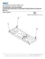
NEC NP-V260X NP115 : ceiling plate instruction - Page 4
For Flush Mounting Applications, For Extension Column Applications - ceiling mount
 |
UPC - 805736036596
View all NEC NP-V260X manuals
Add to My Manuals
Save this manual to your list of manuals |
Page 4 highlights
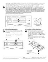
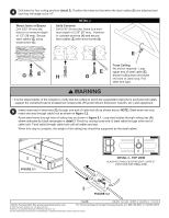
IMPORTANT: Ceiling Tray (A) is designed to fit above a 24" (610 mm) x 24" (610 mm) section of a conventional suspended ceiling system. It may also be mounted above 24" x 48" conventional suspended ceiling. Ceiling runners (see figure 1.1) should have a "T" cross section and a minimum height of 1.5" (38 mm). 1 Place ceiling tray (A) in grid above 24" x 24" or 24" x 48" false ceiling tile so that lip of ceiling tray (A) rests on ceiling runners as shown in figure 1.1. Place in desired position and install 1/4-20 self tapping screws (D) into sides of ceiling tray (A). NOTE: If collar mount plate is positioned to the right, screw (D) can be installed into holes of outside flange on ceiling tray (A). If ceiling runner height is low install screw (D) into lower hole as shown in figure 1.2. Slide collar mount plate to desired position. Using hole in collar mount plate, mark false ceiling tile where hole will be cut. Slide collar mount plate out of the way. Cut out 2.25" hole in false ceiling tile. Slide collar mount plate back into position and tighten all carriage bolts and wing nuts. Remove knock-outs before installing electrical box. KNOCK-OUTS COLLAR MOUNT PLATE A CARRIAGE BOLT OUTSIDE FLANGE D WING NUTS CEILING RUNNER FIGURE 1.1 D FIGURE 1.2 For Flush Mounting Applications 2 From the top down, thread flush mount tube (F) down through retaining collar in adjustable collar mount plate. Snap escutcheon plate (J) around flush mount tube or extension column and slide up until flush with ceiling tile. Skip to step 3. A F For Extension Column Applications 3 From the bottom up, thread extension column (not included) up through retaining collar in adjustable collar mount plate. Align notch in extension column with hole in collar and fasten with M5 x 10 mm penta pin screw (B) using penta pin driver (C). Snap escutcheon plate (J) around flush mount tube or extension column and slide up until flush with ceiling tile. A B 1 1/2" EXTENSION COLUMN (SOLD SEPARATELY) (UL LISTED EXT OR AEC SERIES) Visit the Peerless Web Site at www.peerlessmounts.com 4 of 6 ISSUED: 12-16-04 SHEET #: 120-9015-3 11-05-10 For Technical Support Contact Peerless Mounts at 1-800-729-0307 or 708-865-8870.
-
 1
1 -
 2
2 -
 3
3 -
 4
4 -
 5
5 -
 6
6
 |
 |
