NEC NP-V260X NP115 : ceiling plate instruction - Page 5
Detail 2
 |
UPC - 805736036596
View all NEC NP-V260X manuals
Add to My Manuals
Save this manual to your list of manuals |
Page 5 highlights
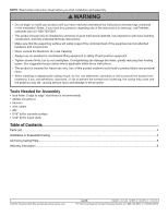
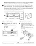
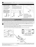
4 Drill holes for four ceiling anchors (detail 2). Position the holes so that when the steel cables (E) are attached and taut they will angle out at 15°. Wood Joists or Beams Drill 5/32" (4 mm) dia. holes to a minimum depth of 1.5" (38 mm). Secure steel cables (E) using wood screw (G) DETAIL 2 Solid Concrete Drill 5/16" (8 mm) dia. holes to a minimum depth of 2.25" (57 mm). Hammer in concrete anchors (H) and secure steel cables (E) with wood screw (G) E GE H Truss Ceiling No anchor required. Loop E upper end of steel cable (E) G around ceiling truss and down into hole of cable loop. Pull steel wire tight. WARNING • It is the responsibility of the installer to verify that the ceiling to which the suspended ceiling kit is anchored will safely support the combined load of all attached components (Projector Mount, Extension Column, etc.) and equipment. 5 Insert loose end of steel wire (E) through one end of cable lock (I) as shown below. NOTE: Steel wires can only insert one way through cable lock as shown in figure 5.2. Route steel wires through hole of ceiling tray as shown in figure 5.1. Loop steel cables through ceiling tray (A) where indicated by black rectangles in detail 3. Finish by routing loose end of steel cable through other end of cable lock. Feed cable through cable lock until all cables are taut. When this step is complete, the weight of the ceiling tray should be supported by the steel cables. E FIGURE 5.1 DETAIL 3 - TOP VIEW BLACK RECTANGLES REPRESENT CORRECT POSITIONS FOR STEEL WIRE I FIGURE 5.2 5 of 6 ISSUED: 12-16-04 SHEET #: 120-9015-3 11-05-10 Visit the Peerless Web Site at www.peerlessmounts.com For Technical Support Contact Peerless Mounts at 1-800-729-0307 or 708-865-8870. © 2007 Peerless Industries, Inc. All rights reserved. Peerless is a registered trademark of Peerless Industries, Inc. All other brand and product names are trademarks or registered trademarks of their respective owners.
-
 1
1 -
 2
2 -
 3
3 -
 4
4 -
 5
5 -
 6
6
 |
 |
