NEC PX-50XM6A 42XM5/50XM6/60XM5 UM - Page 33
CONTROL LOCK settings, INPUT settings, VOLUME settings, REPEAT TIMER function, SINGLE settings,
 |
View all NEC PX-50XM6A manuals
Add to My Manuals
Save this manual to your list of manuals |
Page 33 highlights
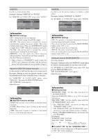
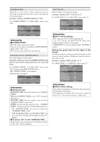
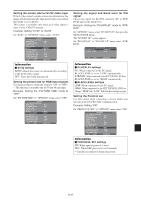
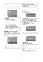
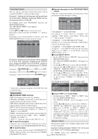
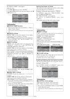
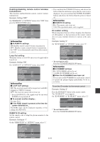
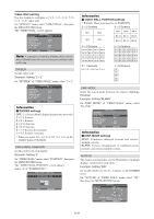
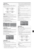
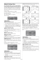
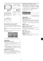
The "REPEAT TIMER" screen appears. Adjust the items. Use the ᮤ and ᮣ buttons to select "SINGLE". Use the L and M buttons to select the item, then press the ᮤ and ᮣ buttons to set. REPEAT TIMER REPEAT TIMER : SINGLE 1 WORK TIME : 00H10M INPUT MODE : VIDEO1 2 WORK TIME INPUT MODE : 00H15M : DVD1 Setting the power on mode This function sets the input mode and the sound volume at the time the power is switched on. Example: Setting the input mode to "VIDEO2" On "OPTION3 " menu, select "PWR.ON MODE ", then press the MENU/ENTER button. The "PWR.ON MODE " screen appears. On "INPUT " of "PWR.ON MODE " menu, select "VIDEO2". The available inputs depend on the setting of input. SEL. ADJ. EXIT RETURN Information Ⅵ REPEAT TIMER function * The two repeat timers run consecutively, i.e., Timer 1- Timer 2-Timer1-Timer2. * This becomes effective when the on-screen menu goes out. Ⅵ SINGLE settings WORK TIME: Set the time duration of the display. Time range is from 1 minute to 24 hours. INPUT MODE: Set the signal that will be displayed. * Set the DIVIDER "OFF" and ID NUMBER "ALL" before the operation. Ⅵ MULTI settings MODE: Select the input mode to be displayed from "SINGLE", "S BY S1~3" and "PICTURE IN PICTURE (BTM LFT~TOP LFT)". WORK TIME: Set the time duration of the display. Time range is from 1 minute to 24 hours. INPUT MODE: Set the signal that will be displayed. Select "MAIN" or "SUB" for "PICTURE IN PICTURE (BTM LFT~TOP LFT)" and "LEFT" or "RIGHT" for "S BY S1~3". Only one signal is selected for "SINGLE". REPEAT TIMER REPEAT TIMER : MULTI 1 MODE : BTM LFT WORK TIME : 04H00M INPUT MODE MAIN : RGB1 SUB : VIDEO1 2 MODE : S BY S1 WORK TIME : 02H30M INPUT MODE LEFT : RGB3 RIGHT : DVD1 SEL. ADJ. EXIT RETURN * Set the DIVIDER "OFF" and ID NUMBER "ALL" before the operation. Ⅵ VIDEO WALL settings DIVIDER: Divide the screens into 1, 2ן2 or 3ן3 sections. WORK TIME: Set the time duration of the display. Time range is from 1 minute to 24 hours. INPUT MODE: Set the signal that will be displayed. * Turn on the AUTO ID and set the DIVIDER (at 1, 2ן2 or 3ן3) before the operations. * In the case of Video Wall, timer No.1 can be used to control all the displays simultaneously. REPEAT TIMER REPEAT TIMER : VIDEO WALL 1 DIVIDER : 1 WORK TIME : 00H03M INPUT MODE : VIDEO1 INPUT VOLUME PWR. ON MODE : VIDEO2 : LAST SEL. ADJ. EXIT RETURN Information Ⅵ INPUT settings LAST: Last mode (the input that was last selected at the time the power was switched off). VIDEO1, 2, 3: VIDEO input mode. RGB1, 2, 3: RGB input mode. DVD/HD1, 2: DVD/HD input mode. MULTI: Multi screen mode. Follow the procedure used for PROGRAM TIMER. See page En-31. PICTURE IN PICTURE SIDE BY SIDE PWR. ON MODE MULTI SCREEN SETTING MULTI MODE : BOTTOM LEFT INPUT MODE MAIN : DVD/HD1 SUB : VIDEO1 PWR. ON MODE MULTI SCREEN SETTING MULTI MODE : SIDE BY SIDE1 INPUT MODE LEFT : DVD/HD1 RIGHT : VIDEO1 SEL. ADJ. EXIT RETURN SEL. ADJ. EXIT RETURN Ⅵ VOLUME settings LAST: Last mode (the volume that was last selected at the time the power was switched off). 0 to 42: The level of sound volume. Enabling/disabling the front panel controls This function enables/disables the front panel controls. Example: Setting "ON" On "CONTROL LOCK" of "OPTION3" menu, select "ON", then press the MENU/ENTER button. OPTION 3 PREVIOUS PAGE TIMER PWR. ON MODE CONTROL LOCK : ON IR REMOTE : ON LOOP OUT : OFF REMOTE ID : ALL ID NUMBER : ALL VIDEO WALL NEXT PAGE SEL. ADJ. EXIT RETURN 3 / 4 Information Ⅵ CONTROL LOCK settings ON: Disables the buttons on the front panel. OFF: Enables the buttons on the front panel. * Even when the CONTROL LOCK is set, the POWER switch will not be locked. * This becomes effective when the on-screen menu goes out. 2 DIVIDER WORK TIME INPUT MODE : 2ן2 : 00H06M : RGB1 SEL. ADJ. EXIT RETURN En-32
-
 1
1 -
2
-
3
-
4
-
5
-
6
-
7
-
8
-
9
-
10
-
11
-
12
-
13
-
14
-
15
-
16
-
17
-
18
-
19
-
20
-
21
-
22
-
23
-
24
-
25
-
26
-
27
-
 28
28 -
 29
29 -
 30
30 -
 31
31 -
 32
32 -
 33
33 -
 34
34 -
 35
35 -
 36
36 -
 37
37 -
 38
38 -
39
-
40
-
41
-
42
-
43
-
44
-
45
-
46
-
47
-
48
-
49
-
50
-
51
-
52
-
53
-
54
-
55
-
56
-
57
-
58
-
59
-
60
-
61
-
62
-
63
-
64
-
65
-
66
-
67
-
68
-
69
-
70
-
71
-
72
-
73
-
74
-
75
-
76
-
77
-
78
-
79
-
80
-
81
-
82
-
83
-
84
-
85
-
86
-
87
-
88
-
89
-
90
-
91
-
92
-
93
-
94
-
95
-
96
-
97
-
98
-
99
-
100
-
101
-
102
-
103
-
104
-
105
-
106
-
107
-
108
-
109
-
110
-
111
-
112
-
113
-
114
-
115
-
116
-
117
-
118
-
119
-
120
-
121
-
122
-
123
-
124
-
125
-
126
-
127
-
128
-
129
-
130
-
131
-
132
-
133
-
134
-
135
-
136
-
137
-
138
-
139
-
140
-
141
-
142
-
143
-
144
-
145
-
146
-
147
-
148
-
149
-
150
-
151
-
152
-
153
-
154
-
155
-
156
-
157
-
158
-
159
-
160
-
161
-
162
-
163
-
164
-
165
-
166
-
167
-
168
-
169
-
170
-
171
-
172
-
173
-
174
-
175
-
176
-
177
-
178
-
179
-
180
-
181
-
182
-
183
-
184
-
185
-
186
-
187
-
188
-
189
-
190
-
191
-
192
-
193
-
194
-
195
-
196
-
197
-
198
-
199
-
200
-
201
-
202
-
203
 |
 |
