Nady PEM-1000 Manual - Page 3
Quick User Control Guide - receiver
 |
View all Nady PEM-1000 manuals
Add to My Manuals
Save this manual to your list of manuals |
Page 3 highlights
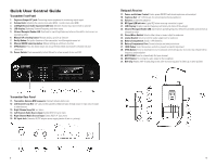
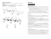
Quick User Control Guide Transmitter Front Panel 1. Earphone Output 1/4" jack: Connecting stereo earphones for monitoring output signal 2. Volume Knob: Adjusting the volume clock-wise (MAX), counter clock-wise (MIN) 3. Left/Right Source Audio Input Level LCD tree: Indicates if audio input source level is optional 4. LCD display: Displaying Channel/Frequency, and other status 5. Infrared Receptor/Sender LED: Synchronizes operatingnfrequency between transmitter and receiver as selected by either 6. Manual UP selecting button: Manual setting up with up direction 7. Set Up Button: Set up the functions of the transmitter/ scroll through the menu list 8. Manual DOWN selecting button: Manual setting up with down direction 9. SYNC Button: Press this button down can set up the transmitter and receiver's infrared link and connection 10. Power Switch: Press momentarily to turn ON and for a few seconds to turn unit OFF Bodypack Receiver 17. Power and Volume Control: Combo power ON/OFF switch and earphones volume adjust 18. Earphone Out: 1/8" (3.5mm) jack for connecting monitoring earphones 19. Antenna: permanently attached 20. RF Signal LED Indicator: Lights RED when receiving transmitter's signal 21. LCD Display: Displays selected frequency and battery life status (0 Bar=Empty) 22. Infrared Receptor/Sender LED: Synchronizes operating frequency between transmitter and receiver as selected by either 23. Stereo/Mono Switch: Selects either stereo or mono output to earphones 24. Limiter Switch: Select to limit the audio output level to earphones 25. Battery Compartment: Holds 2 x AA Betteries 26. Battery Compartment Door: Covers batteries and selection buttons 27. LOCK Button: Locks the receiver controls to prevent accidental adjustment 28. SYNC Button: Press to download receiver's Autoscan selected frequency to receiver via infrared link for frequency synchronization 29. AUTOSCAN: Press to automatically find open channel 30. MUTE Button: For muting the audio output to the headphone 31 . Belt Clip: Rotates 180o for attaching to belt with receiver's top panel in either up or down position Transmitter Rear Panel 11. Transmitter Antenna BNC connector: Connect antenna before use 12 Left Channel Loop Out: 1/4" jack provides parallel unbalanced pass-through output of input source signal to other devices 13. Right Channel Loop Out: see above 14. Left Channel Audio Source Input: Combo XLR/1/4" jack, mono 15. Right Channel Audio Source Input: Combo XLR/1/4" jack, mono 16. DC Input Jack: Connects AC/DC adapter power supply (center of jack is + polarity) 5 6
-
 1
1 -
 2
2 -
 3
3 -
 4
4 -
 5
5 -
 6
6 -
 7
7 -
 8
8
 |
 |
