Netgear AFT603 Installation Guide - Page 8
When the screw is fully tightened, the yellow band around the, captive screw is completely hidden.
 |
View all Netgear AFT603 manuals
Add to My Manuals
Save this manual to your list of manuals |
Page 8 highlights
6. Using both hands, push both handles toward the center of the switch blade, as shown. Supervisor XCM8948 OOB PSWtatRu/s Reset Console USB 1 2 3 4 5 6 7 8 9 10 PoE 11 (Max 60W 12 per port): Off 13 = no PD 14 Green = Po1E5powere1d6Yellow 17 = PoE 18 fault RJ4159SPD/Lin2k0/Act 21 Mode: 22 Green = link 23 at 1G 24 Yellow = Link at 25 10/100M 26 Blink = 27 ACT 28 29 30 31 32 33 34 35 36 37 38 39 40 41 42 43 44 45 46 47 48 7. Use your fingers or a screwdriver to turn the front panel screws on each injector-ejector handle clockwise and completely down. When the screw is fully tightened, the yellow band around the captive screw is completely hidden. 8
-
 1
1 -
2
-
 3
3 -
 4
4 -
 5
5 -
 6
6 -
 7
7 -
 8
8 -
 9
9 -
 10
10 -
 11
11 -
 12
12 -
 13
13 -
14
-
15
-
16
-
17
-
18
-
19
-
20
 |
 |

8
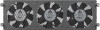
6.
Using both hands, push both handles toward the center of the
switch blade, as shown.
7.
Use your fingers or a screwdriver to turn the front panel screws
on each injector-ejector handle clockwise and completely
down.
When the screw is fully tightened, the yellow band around the
captive screw is completely hidden.