Netgear GS305P Installation Guide
Netgear GS305P Manual
 |
View all Netgear GS305P manuals
Add to My Manuals
Save this manual to your list of manuals |
Netgear GS305P manual content summary:
- Netgear GS305P | Installation Guide - Page 1
app. Note: Because this is an unmanaged switch, you cannot configure or manage it in NETGEAR Insight. 2. Connect the switch GS305PP Access point Router VoIP phone Internet Security cameras Sample connections Internet PoE Note: The GS305PP switch supports both 802.3at (PoE+) and 802.3af - Netgear GS305P | Installation Guide - Page 2
holes on the bottom panel. Note: GS305PP screws are 4.2 mm in diameter, 25 mm in length. Support Thank you for purchasing this NETGEAR product. You can visit https://www.netgear.com/support/ to register your product, get help, access the latest downloads and user manuals, and join our community. We
-
 1
1 -
 2
2
 |
 |
Installation Guide
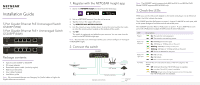
1. Register with the NETGEAR Insight app
1.
Search for
NETGEAR Insight
and download the latest app.
2.
Set up a NETGEAR account if you do not have one.
3.
Tap the menu in the upper-left corner.
4.
Tap
REGISTER ANY NETGEAR DEVICE
.
5.
Use the camera on your mobile device to scan the serial number bar code,
or enter the serial number located on the bottom of the switch.
6.
Tap
GO
.
The switch is registered and added to your account. You can now view the
switch in the NETGEAR Insight app.
Note:
Because this is an unmanaged switch, you cannot configure or manage it
in NETGEAR Insight.
2. Connect the switch
VoIP phone
Internet
GS305PP
Internet
PoE
Sample connections
Security cameras
Access point
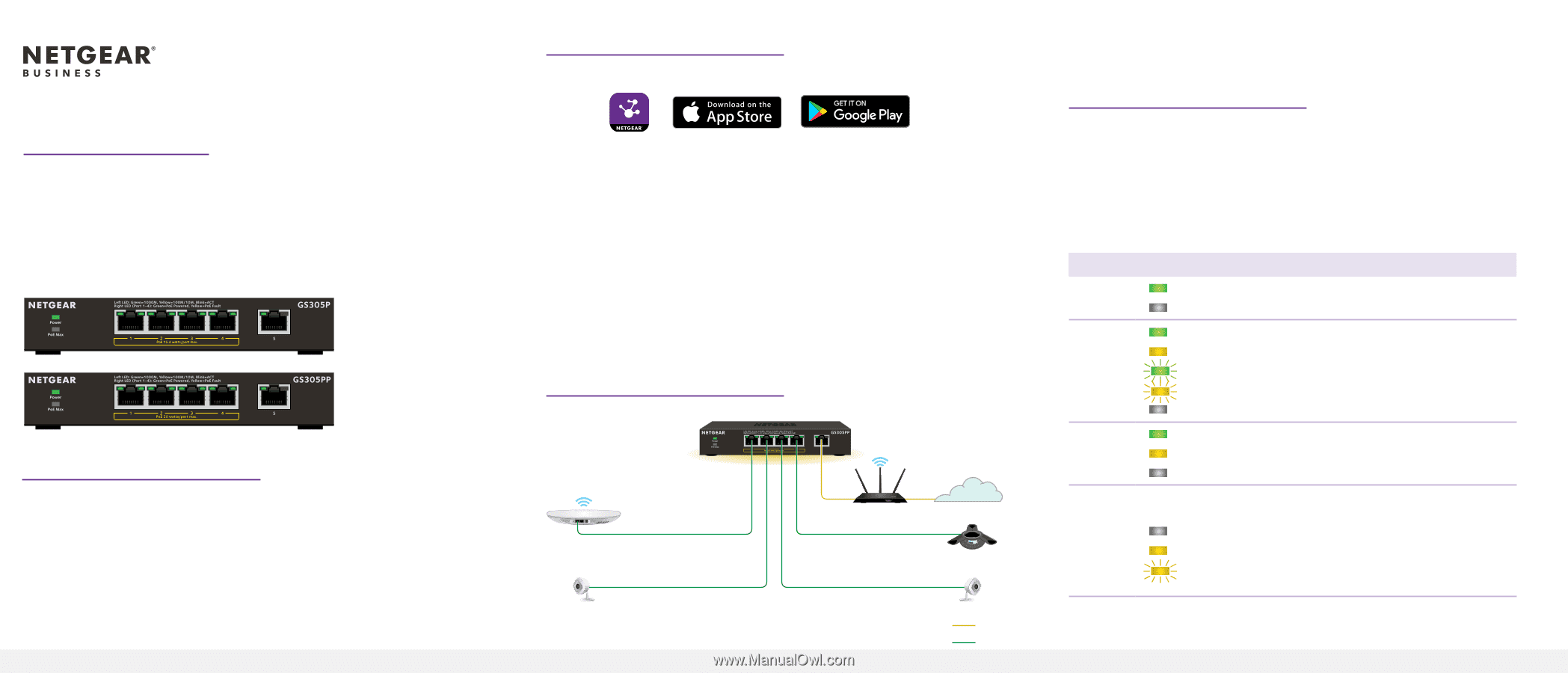
5-Port Gigabit Ethernet PoE Unmanaged Switch
GS305P (55W)
5-Port Gigabit Ethernet PoE+ Unmanaged Switch
GS305PP (83W)
Package contents
•
Switch model GS305P or GS305PP
•
DC power adapter
•
Detachable power cable
(varies by region)
•
Wall-mount kit screws
•
Four rubber footpads
•
Installation guide
Note:
We recommend that you use Category 5e (Cat 5e) cable or higher for
Gigabit Ethernet connections.
Note:
The GS305PP switch supports both 802.3at (PoE+) and 802.3af (PoE).
Model GS305P supports 802.3af (PoE) only.
3. Check the LEDs
When you connect the power adapter to the switch and plug it into an electrical
outlet, the LEDs indicate the status.
The GS305P provides PoE power on ports 1–4 up to 15.4W PoE to each port, with
a PoE power budget of 55.5W across all active PoE ports.
The GS305PP provides PoE+ or PoE power on ports 1–4 up to 30W PoE to each
port, with a PoE power budget of 83W across all active PoE ports.
LED
Description
Power
On
. The switch is receiving power.
Off
. The switch is not receiving power.
Ports 1–5
left port
On
.1000 Mbps link on this port.
On
. 100 Mbps or 10 Mbps link on this port.
Blinking
. 1000 Mbps activity on this port.
Blinking
. 100 Mbps or 10 Mbps activity on this port.
Off
. No link is detected on this port.
Ports 1–4
right port
On
. PoE is in use.
On
. PoE halted.
Off
. PoE is not in use on this port.
PoE Max
The PoE Max LED indicates the status of the PoE budget on the
switch:
Off
. Sufficient. More than 7W of PoE power is available.
On
. Less than 7W of PoE power is available.
Blinking
. At least once during the previous two minutes, less
than 7W of PoE power was available.
Router