Netgear GS305P Installation Guide - Page 2
Mount the switch on a wall, Support, PoE considerations, PoE Troubleshooting - manual
 |
View all Netgear GS305P manuals
Add to My Manuals
Save this manual to your list of manuals |
Page 2 highlights
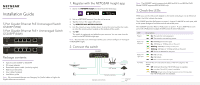
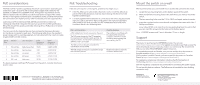
PoE considerations The PoE and PoE+ power supplied by the switch is prioritized in ascending port order (from port 1 to port 4), with a total power budget of 55.5 watts for the GS305P, and 83W for the GS305PP switch. If the power requirements for the attached powered devices (PDs) exceed the total power budget of the switch, the PD on the highest-numbered port is disabled to make sure that the PDs that are connected to the higher-priority, lower-numbered ports are supported first. Just because a PD is listed as an 802.3at PoE powered device does not necessarily mean that it requires the maximum power limit of the specification. Many PDs require less power, potentially allowing all four PoE ports to be active simultaneously. You can override the detected device class and specify the power allocation for the device connected to each port. The following table shows the standard power ranges with no overrides applied, and calculated with the maximum cable length of 328 feet (100 meters). Device Class 0 1 2 3 4 Standard PoE and PoE+ PoE and PoE+ PoE and PoE+ PoE and PoE+ PoE+ only Class Description Default power (full) Very low power Low power Mid power High power Power Reserved by the Device 15.4W 4.0W 7.0W 15.4W 30.0W Power Delivered to the Device 0.44W-12.95W 0.44W-3.84W 3.84W-6.49W 6.49W-12.95W 12.95W-25.5W If a device receives insufficient PoE power from the switch, consider attaching a shorter cable. PoE Troubleshooting Here are some tips for correcting PoE problems that might occur: • If the PoE Max LED is solid amber, disconnect one or more PoE devices to prevent PoE oversubscription. Start by disconnecting the device from the highest-numbered port. • For each powered device (PD) that is connected to the switch, the associated right port LED on the switch lights solid green. If the right port LED lights solid amber, a PoE fault occurred and PoE halted because of one of the conditions listed in the following table. PoE Fault Condition A PoE-related short circuit occurred on the port. The PoE power demand of the PD exceeded the maximum level that the switch permits. The maximum level is 15.4 for a PoE connection or 30W for a PoE+ connection The PoE current on the port exceeded the classification limit of the PD. The PoE voltage of the port is outside the range that the switch permits Possible Solution The problem is most likely with the attached PD. Check the condition of the PD or restart the PD by disconnecting and reconnecting the PD. Restart the switch to see if the condition resolves itself. December 2019 © NETGEAR, Inc., NETGEAR and the NETGEAR Logo are trademarks of NETGEAR, Inc. Any non‑NETGEAR trademarks are used for reference purposes only. Mount the switch on a wall We recommend that you use the wall-mount screws that came with the switch. 1. Locate the two mounting holes on the bottom panel of the switch. 2. Mark and drill two mounting holes in the wall where you want to mount the switch. The two mounting holes must be 1.53 in. (38.9 mm) apart, center-to-center. 3. Insert the supplied anchors into the wall and tighten the screws with a No. 2 Phillips screwdriver. Leave about 0.125 in. (4 mm) of each screw protruding from the wall so that you can insert the screws into the holes on the bottom panel. Note: GS305PP screws are 4.2 mm in diameter, 25 mm in length. Support Thank you for purchasing this NETGEAR product. You can visit https://www.netgear.com/support/ to register your product, get help, access the latest downloads and user manuals, and join our community. We recommend that you use only official NETGEAR support resources. Si ce produit est vendu au Canada, vous pouvez accéder à ce document en français canadien à https://www.netgear.com/support/download/. (If this product is sold in Canada, you can access this document in Canadian French at https://www.netgear.com/support/download/.) For regulatory compliance information including the EU Declaration of Conformity, visit https://www.netgear.com/about/regulatory/. See the regulatory compliance document before connecting the power supply. Do not use this device outdoors. The PoE source is intended for intra building connection only. NETGEAR, Inc. 350 East Plumeria Drive San Jose, CA 95134, USA NETGEAR INTERNATIONAL LTD Floor 1, Building 3, University Technology Centre Curraheen Road, Cork, T12EF21, Ireland
-
 1
1 -
 2
2
 |
 |
