Netgear GSM7328Sv1 7000 Series VRRP Configuration
Netgear GSM7328Sv1 - ProSafe 24+4 Gigabit Ethernet L3 Managed Stackable Switch Manual
 |
View all Netgear GSM7328Sv1 manuals
Add to My Manuals
Save this manual to your list of manuals |
Netgear GSM7328Sv1 manual content summary:
- Netgear GSM7328Sv1 | 7000 Series VRRP Configuration - Page 1
master and forward packets destined to the VRRP IP. VRRP - GSM/FSM 7300 series: guide you on how to set up VRRP between two Layer 3 switches, so they may dynamically adapt to a loss of connectivity to one of the switches and seamlessly redirect host traffic towards another a backup router - Netgear GSM7328Sv1 | 7000 Series VRRP Configuration - Page 2
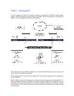
the hosts will be in the 192.168.2.0 network, the Virtual Router address will be configured to be 192.168.2.24 NOTE: VRRP can use the IP address of one of the physical interfaces as the Virtual Router IP. In this case, VRRP could use the IP address 192.168.2.1 instead of 192.168.2.24. Whether to use - Netgear GSM7328Sv1 | 7000 Series VRRP Configuration - Page 3
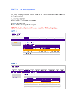
SWITCH 1 - VLAN Configuration The switch has been configured with two VLANs; VLAN 2 will be the access VLAN, VLAN 3 will be the gateway VLAN VLAN 2: 192.168.2.1/24 Ports in VLAN 2: 21 untagged, 22 untagged VLAN 3: 192.168.3.1/24 Ports in VLAN 3: 23 untagged, 24 untagged NOTE: The VLAN configuration - Netgear GSM7328Sv1 | 7000 Series VRRP Configuration - Page 4
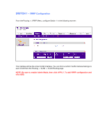
SWITCH 1 - VRRP Configuration From the Routing -> VRRP Menu, configure Switch 1 in the following manner: The interface will be the virtual VLAN interface. You can find out which VLAN interface belongs to each VLAN from the Routing -> VLAN -> VLAN Routing page. NOTE: Be sure to enable Admin Mode, - Netgear GSM7328Sv1 | 7000 Series VRRP Configuration - Page 5
SWITCH 2 - VLAN Configuration The switch has been configured with two VLANs; VLAN 2 will be the access VLAN, VLAN 4 will be the gateway VLAN VLAN 2: 192.168.2.2/24 Ports in VLAN 2: 21, 22 VLAN 4: 192.168.4.1/24 Ports in VLAN 3: 23, 24 NOTE: The VLAN configuration will be done through the VLAN - Netgear GSM7328Sv1 | 7000 Series VRRP Configuration - Page 6
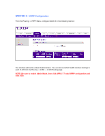
SWITCH 2 - VRRP Configuration From the Routing -> VRRP Menu, configure Switch 2 in the following manner: The interface will be the virtual VLAN interface. You can find out which VLAN interface belongs to each VLAN from the Routing -> VLAN -> VLAN Routing page. NOTE: Be sure to enable Admin Mode, - Netgear GSM7328Sv1 | 7000 Series VRRP Configuration - Page 7
DGFV338 - Routing configuration In each router, we will have to add a route that directs them back to the 192.168.2.0 LAN. Alternatively this could be done by configuring RIP on the Switches and Routers. Router 1: Router 2: - Netgear GSM7328Sv1 | 7000 Series VRRP Configuration - Page 8
Master from the VRRP menu. Once we know which of our switches is the primary, we will start a ping stream from our host to a public IP address. As an example, "ping 4.2.2.2 -t" While the pings are responding, unplug the power of whichever switch is serving as the current VRRP master. You will notice - Netgear GSM7328Sv1 | 7000 Series VRRP Configuration - Page 9
example has a single internet connection, but will use two VRRP sessions. One between the hosts and the router, and one between the router and the hosts; that way, if the master switch fails, both the router and the hosts will be able to get to the other side of the network. NOTE: Because - Netgear GSM7328Sv1 | 7000 Series VRRP Configuration - Page 10
CASE 3 - Load Balancing through VRRP In this example we have two Internet connections provided by FVS338 routers; Router 1 will be the gateway for the hosts connected to Switch 1, and Router 2 will be the gateway for the hosts connected to Switch 2. In the event communication breaking between one of
-
 1
1 -
 2
2 -
 3
3 -
 4
4 -
 5
5 -
 6
6 -
 7
7 -
8
-
9
-
10
 |
 |

VRRP – Definition:
VRRP, which stands for Virtual Router Redundancy Protocol, specifies an election system
between different Layer 3 devices to represent a default gateway for the devices that will connect
to them.
As an example, if three different Layer 3 devices are configured to use VRRP, all the hosts could
have the same default gateway IP (In this document we’ll refer to it as VRRP IP). Any of these
three Layer 3 devices would be able to forward and respond to packets that come to this VRRP
IP. However, at any given time, only one will be the master and the other two will be standing by
as backup. Should the master unit fail, an election will occur to decide which of the two Switches
will become master and forward packets destined to the VRRP IP.
VRRP – GSM/FSM 7300 series:
Although there are many different scenarios where VRRP may be used to create redundancy in
your network, this document will guide you on how to set up VRRP between two Layer 3
switches, so they may dynamically adapt to a loss of connectivity to one of the switches and
seamlessly redirect host traffic towards another a backup router.
At the end of this document we will briefly describe some of the alternative deployment scenarios.