Netgear GSM7328Sv1 7000 Series VRRP Configuration - Page 10
Case 3
 |
View all Netgear GSM7328Sv1 manuals
Add to My Manuals
Save this manual to your list of manuals |
Page 10 highlights
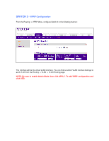
CASE 3 - Load Balancing through VRRP In this example we have two Internet connections provided by FVS338 routers; Router 1 will be the gateway for the hosts connected to Switch 1, and Router 2 will be the gateway for the hosts connected to Switch 2. In the event communication breaking between one of the Access Switches (Switch 1 and 2) and one of the Core Switches (Switch 3 and 4), the other core switch will become master for both VRRP sessions and accordingly route the traffic to the correct router and to the internet. NOTE: Because there is a loop in this topology, a similar deployment will require proper configuration of STP.
-
 1
1 -
2
-
3
-
4
-
 5
5 -
 6
6 -
 7
7 -
 8
8 -
 9
9 -
 10
10
 |
 |

CASE 3 –
Load Balancing through VRRP
In this example we have two Internet connections provided by FVS338 routers; Router 1 will be
the gateway for the hosts connected to Switch 1, and Router 2 will be the gateway for the hosts
connected to Switch 2.
In the event communication breaking between one of the Access Switches (Switch 1 and 2) and
one of the Core Switches (Switch 3 and 4), the other core switch will become master for both
VRRP sessions and accordingly route the traffic to the correct router and to the internet.
NOTE:
Because there is a loop in this topology, a similar deployment will require proper
configuration of STP.