NordicTrack 9800 I Treadmill User Manual - Page 38
Part List
 |
View all NordicTrack 9800 I Treadmill manuals
Add to My Manuals
Save this manual to your list of manuals |
Page 38 highlights
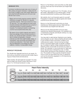
PART LIST R0204A To locate the parts listed below, refer to the EXPLODED DRAWING on pages 39 to 41. Key No. Qty. Description Key No. Qty. Description 1 1 Left Foot Pad 2 1 Hood 3 1 Rear Endcap (Left) 4 1 Drive Roller 5 2 Rear Roller Guard (Right) 6 25 Guard/Endcap Screw 7 4 Incline Motor Bushing 8 4 Platform Screw (Rear) 9 2 Incline Motor Bolt 10 1 Cup Holder 11 2 Mid Frame Endcap 12 1 Power Cord Bracket 13 4 Roller Guard Cage Nut (Front) 14 2 Belt Guide 15 33 Bracket Screw 16 2 Front Roller Adj. Bolt 17 2 Front Roller Adj. Washer 18 1 Front Endcap (Left) 19 1 Right Foot Pad 20 1 Walking Belt 21 1 Walking Platform 22 1 Lift Frame 23 8 Incline Motor Nut 24 4 Resistor Washer 25 2 Resistor Nut 26 1 Controller Box 27 1 Torsion Bar 28 2 Resistor Screw 29 2 Incline Motor 30 1 Cord Caution Decal 31 3 Speed Disk Screw 32 2 Ferrite Box 33 1 TV Cable (Long) 34 1 Strain Relief Bracket 35 4 Access Cover Screw 36 2 Receptical Bolt 37 1 TV Cable (Short) 38 1 Wiring Plate (Left) 39 4 Wheel Bolt 40 4 Wheel 41 2 Chest Pulse Foam 42 1 Jack 43 1 Power Cord 44 1 Power Cord Receptacle 45 2 Receptical Nut 46 1 On/Off Circuit Breaker 47 2 Incline Motor Spacer 48 1 Wiring Plate (Right) 49 1 Power Wire Harness (Right) 50 4 Base Pad Screw 51 2 52 1 53 2 54 2 55 1 56 2 57 1 58 1 59 1 60 2 61 2 62 2 63 1 64 1 65 8 66 2 67 4 68 4 69 1 70 4 71 1 72 1 73 5 74 2 75 1 76 1 77 1 78 1 79 1 80 1 81 1 82 8 83 1 84 1 85 1 86 1 87 4 88 1 89 1 90 1 91 8 92 2 93 4 94 1 95 2 96 1 97 4 98 26 99 4 100 2 Base Pad Base Frame Incline Motor Bolt (Lower) Caution Decal Roller Pulley Belt Guide Bolt Power Supply Box High Voltage Decal Electronics Cover Frame Pivot Bolt Frame Pivot Bushing Frame Spacer J-Bolt Caution Decal Front Endcap (Right) Handrail Cover Cage Nut Rear Leveling Leg Motor Bolt Motor Bushing Drive Motor Motor Nut Hazardous Voltage Decal Motor Isolator Hood Screw Sensor Bracket Screw Sensor Bracket Speed Sensor Speed Disk Front Roller Motor Belt Idler Pulley Bolt Idler Pulley Incline Motor Washer/Drive Motor Washer Motor Pulley Idler Pivot Bolt Idler Arm J-Bolt Wire Tie Clip Green Ground Wire (12") Console Key/Clip Upright Cap Screw Upright Cap Handrail Bolt Handrail Handrail Endcap Left Upright Pulse Sensor Small Screw Pulse Sensor Screw Pulse Housing Screw 37
-
 1
1 -
2
-
3
-
4
-
5
-
6
-
7
-
8
-
9
-
10
-
11
-
12
-
13
-
14
-
15
-
16
-
17
-
18
-
19
-
20
-
21
-
22
-
23
-
24
-
25
-
26
-
27
-
28
-
29
-
30
-
31
-
32
-
 33
33 -
 34
34 -
 35
35 -
 36
36 -
 37
37 -
 38
38 -
 39
39 -
 40
40 -
 41
41 -
 42
42 -
 43
43
 |
 |
