NordicTrack Cx 998 Elliptical English Manual - Page 22
How To Remove The Side Shields And The, Flywheel Covers, How To Adjust The Reed Switch, How - belt instructions
 |
View all NordicTrack Cx 998 Elliptical manuals
Add to My Manuals
Save this manual to your list of manuals |
Page 22 highlights
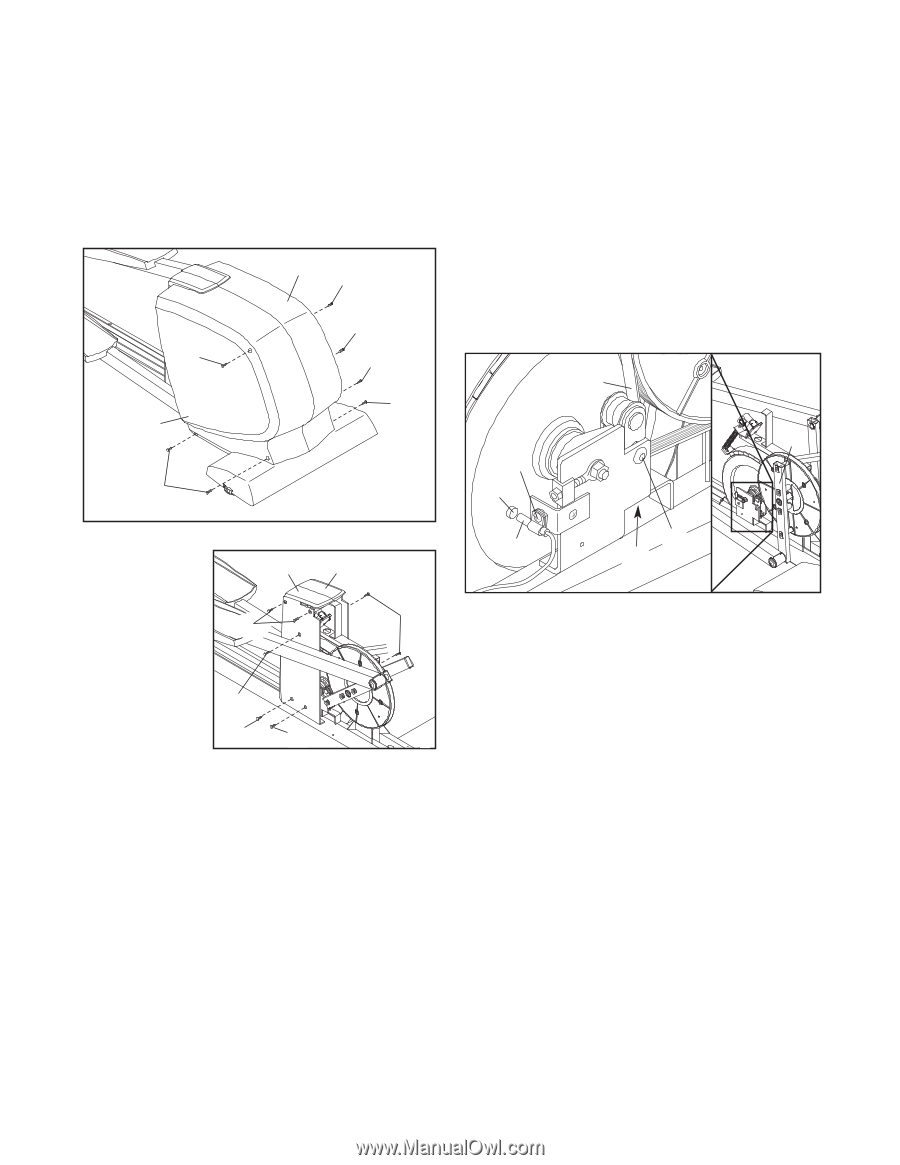
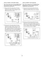
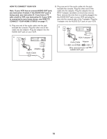
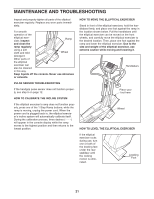
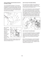
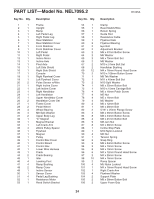
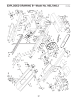
HOW TO REMOVE THE SIDE SHIELDS AND THE FLYWHEEL COVERS The Left and Right Side Shields (15, 16) must be removed before the reed switch or the drive belt can be adjusted. To remove the Side Shields, remove the indicated Screws (69, 95, 97). Note which hole each Screw is removed from; the Screws will later need to be reattached in the same holes. Carefully separate and remove the Side Shields. 16 95 95 15 69 97 69 69 HOW TO ADJUST THE REED SWITCH If the console does not display correct feedback, the reed switch should be adjusted. To adjust the reed switch, first see the instructions at the left and remove the side shields and the flywheel covers. Next, see the drawing below. Locate the Reed Switch (55). Turn the Left Crank Arm (34) until the Magnet (37) is aligned with the Reed Switch. Loosen, but do not remove, the indicated Screw (98). Slide the Reed Switch slightly closer to or away from the Magnet, and then retighten the Screw. Turn the Left Crank Arm for a moment. Repeat until the console displays correct feedback. When the Reed Switch is correctly adjusted, reattach the side shields and the flywheel covers. 113 34 98 37 Next, the Right and Left 19 18 Flywheel Covers (18, 19) must be 69 removed. 97 Remove the indicated Screws (69, 97, 101) from the 69 Flywheel Covers. Note 101 69 which hole each Screw is removed from; the Screws will later need to be reat- tached in the same holes. Carefully separate and remove the Flywheel Covers. 55 75 74 HOW TO ADJUST THE DRIVE BELT If you can feel the pedals slip while you are pedaling, even when the resistance is adjusted to the highest setting, the drive belt may need to be adjusted. To adjust the drive belt, first see the instructions at the left and remove the side shields and the flywheel covers. Next, see the drawing above. Loosen the indicated Bolt (75). Turn the indicated Screw (74) clockwise until the Drive Belt (113) is properly tightened, and then retighten the Bolt (75). Then, reattach the side shields and the flywheel covers. 22
-
 1
1 -
2
-
3
-
4
-
5
-
6
-
7
-
8
-
9
-
10
-
11
-
12
-
13
-
14
-
15
-
16
-
 17
17 -
 18
18 -
 19
19 -
 20
20 -
 21
21 -
 22
22 -
 23
23 -
 24
24 -
 25
25 -
 26
26 -
 27
27 -
28
 |
 |