NordicTrack Gx 2.5 Bike English Manual - Page 6
Assembly
 |
View all NordicTrack Gx 2.5 Bike manuals
Add to My Manuals
Save this manual to your list of manuals |
Page 6 highlights
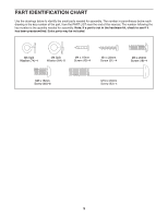
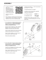
ASSEMBLY •• To watch an assembly video, go to http://productvideo.co/ assembly/nordictrack or use your mobile phone or smartphone to read the QR code at the right. •• Assembly requires two persons. •• Place all parts in a cleared area and remove the packing materials. Do not dispose of the packing materials until you nish all assembly steps. •• Left parts are marked “"L”" or “"Left”" and right parts are marked “"R”" or “"Right.”" •• To identify small parts, see page 5. •• In addition to the included tool(s), assembly requires the following tools: one Phillips screwdriver one adjustable wrench Assembly may be easier if you have a set of wrenches. To avoid damaging parts, do not use power tools. 1. Set a sturdy piece of packing material under the rear of the Frame (1). Have a second person 1 hold the Frame to prevent it from tipping while you complete this step. Identify the Rear Stabilizer (3). Note: The Rear Stabilizer does not have wheels; the Front Stabilizer (not shown) does have wheels. Orient the Rear Stabilizer (3) so that the welded tubes are facing away from the Frame (1). Attach the Rear Stabilizer (3) to the Frame (1) with two M10 x 95mm Screws (53). Remove the packing material. 53 3 1 Welded Tubes 2. Set a sturdy piece of packing material under the front of the Frame (1). Have a second person 2 hold the Frame to prevent it from tipping while you complete this step. Orient the Front Stabilizer (2) so that the wheels are facing away from the Frame (1). Attach the Front Stabilizer (2) to the Frame (1) with two M10 x 95mm Screws (53). Remove the packing material. Wheel 2 53 1 6
-
 1
1 -
 2
2 -
 3
3 -
 4
4 -
 5
5 -
 6
6 -
 7
7 -
 8
8 -
 9
9 -
 10
10 -
 11
11 -
 12
12 -
13
-
14
-
15
-
16
-
17
-
18
-
19
-
20
-
21
-
22
-
23
-
24
-
25
-
26
-
27
-
28
 |
 |
