Oki M84Pro Quick Start Guide - Page 13
M-84PRO Quick Guide, Pg 13, Troubleshooting, Pg 10, Operation Panel, PRINT, OFFSET, PITCH, DISPLAY, - ribbon sensor
 |
View all Oki M84Pro manuals
Add to My Manuals
Save this manual to your list of manuals |
Page 13 highlights
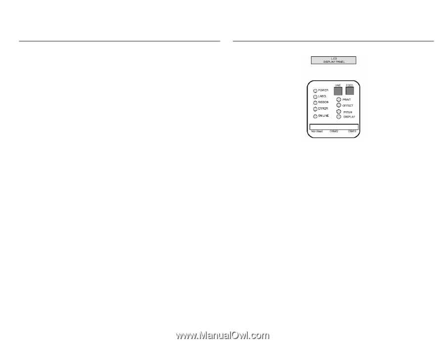
M-84PRO Quick Guide Pg 13 M-84PRO Quick Guide Pg 10 Troubleshooting Initial Checklist 1. Is the printer powered up and ON-LINE? 2. Is the ERROR light on the front panel off? If this light is on, it may mean the Print Head Assembly or the Label Hold-Down is not closed and latched in position. 3. Are the LABEL and RIBBON lights on the front panel off? If these lights are on, the labels or ribbons may be incorrectly loaded. Using the IEEE1284 Parallel Interface 1. Is the IEEE1284 printer cable connected securely to your parallel port (DB-25S Female) on the PC and to the Parallel Interface connector on the printer? 2. Does the Parallel interface cable used meet IEEE1284 specifications? If it does not and you are connected to an IEEE1284 or ECP parallel port on the computer, the printer may not be able to communicate correctly. 3. Is there more than one parallel interface port on your PC (LPT1, LPT2, etc)? If so, make sure you are sending data out the correct port. 4. Is the IEEE1284 Interface Module installed in the printer? Older versions of the Parallel Interface module will not work correctly in the M-84PRO printers. 5. When you send the print job to the printer, and it does not respond, do you get an error message on your PC that says "Device Fault" or something similar? This may mean that the computer doesn't know the printer is there. Verify that: a. Both ends of the cable are securely inserted into their respective connectors. b. The printer is ONLINE. c. The cable is not defective. There are other things that can cause this error message on your computer, but at this stage, a defective cable may be one of the reasons. 6. When you send the print job to the printer and it does not respond, and there is no error message on the PC: a. Check your data stream for some of the basics. Is your job framed as follows? A - DATA - Z b. Verify that you've included all required parameters in the data stream. c. Verify the following: You have not typed a "0" (zero) for an "O" (letter) or vice versa. You have not missed any characters where they're needed. Make sure all printer command codes are capital letters. Operation Panel The M-84PRO Operator Panel consists of five LED indicators, two momentary contact switches, three DIP switches, four adjustment potentiometers and one LCD Display. All of these are accessible from the front of the printer. They are used to set the printer operating parameters and to indicate the status of the printer to the operator. After you power on the printer, familiarize yourself with the keys and indicators as it will help you understand the configuration process. PRINT OFFSET PITCH DISPLAY POWER LABEL RIBBON ERROR ON LINE LINE Potentiometer to adjust print darkness (fine tuning). Potentiometer to adjust amount of back/forward feed for dispenser/cutter/tear-off position (+/- 3.75 mm). Potentiometer to adjust home position of the label (+/- 3.75 mm). Affects stop position of label feed, print position and dispense position. Potentiometer to adjust the contrast of the LCD display. LED, illuminated when power is on. LED, illuminated when the label supply is not detected. LED, illuminated when the ribbon motion sensor does not detect any ribbon motion (ribbon out condition). LED, illuminated when there is a system fault such as an open print head. LED, illuminated when printer is ready to receive data. Toggled on/off with LINE key. Momentary switch. Pressing this key toggles the printer between the on-line and off-line mode. When the printer is on-line, it is ready to receive data from the host. This key acts as a pause during a print job by taking the printer off-line. It can also be used as a Pause function key to stop the printer during the printing process.
-
 1
1 -
2
-
3
-
4
-
5
-
6
-
7
-
 8
8 -
 9
9 -
 10
10 -
 11
11 -
 12
12 -
 13
13 -
 14
14
 |
 |