Onkyo HT-R540 Owner Manual - Page 12
Rear Panel, VIDEO 1 IN/OUT and VIDEO 2 - receiver
 |
View all Onkyo HT-R540 manuals
Add to My Manuals
Save this manual to your list of manuals |
Page 12 highlights
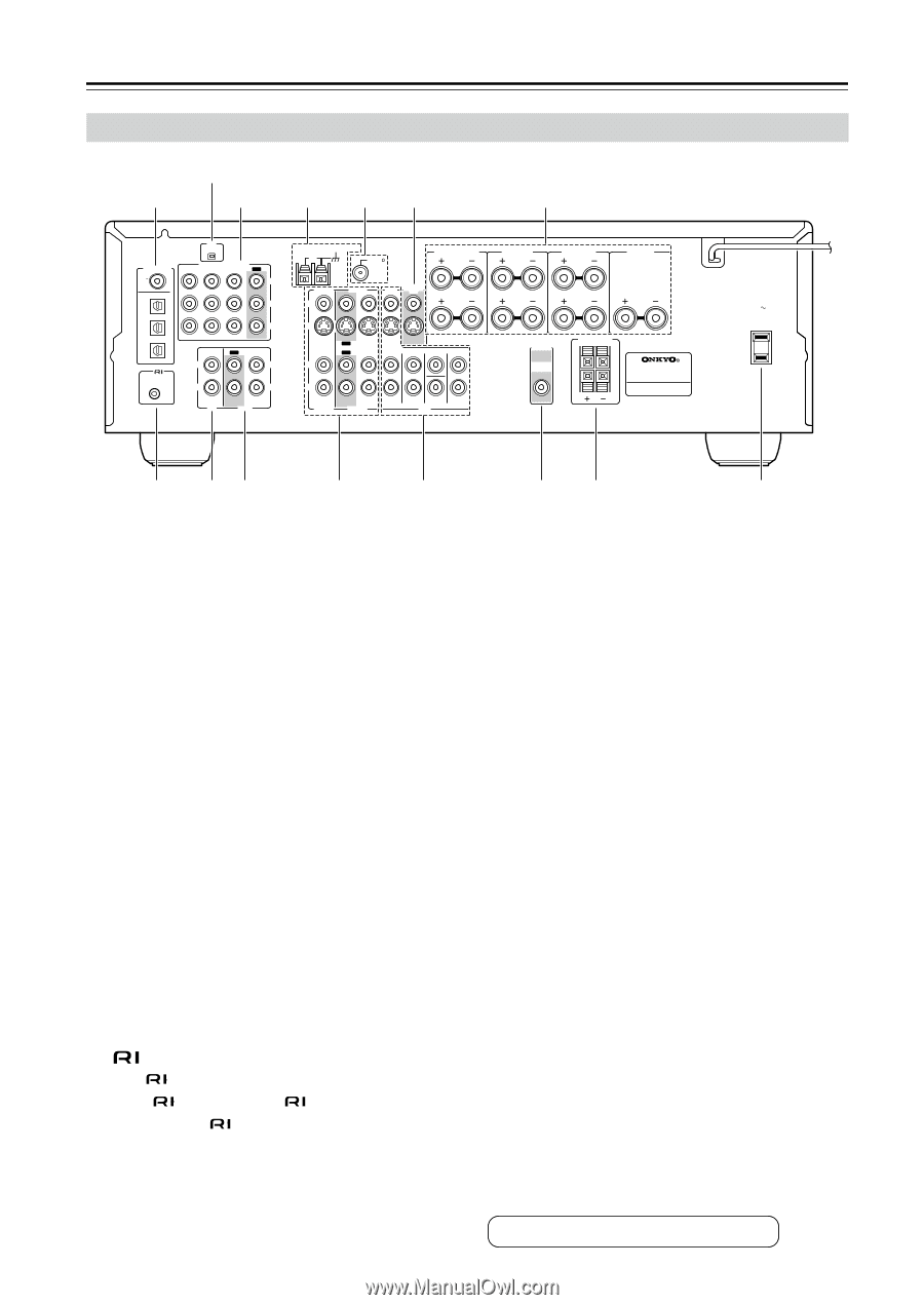
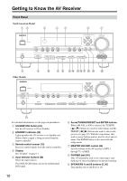
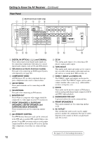
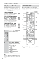
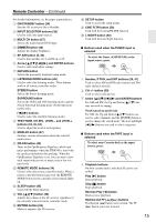
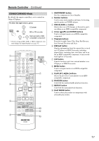
Getting to Know the AV Receiver-Continued Rear Panel B (North American model only) 1 3 4 56 7 XM DIGITAL IN COA XIAL OPTICAL 1 COMPONENT VIDEO VIDEO 2 IN VIDEO 1 IN DVD IN OUT Y PB 2 PR 3 REMOTE CONTROL IN OUT IN L L R CD R TAPE ANTENNA AM FM 75 SURROUND BACK SPEAKERS L VIDEO 2 V VIDEO 1 DVD MONITOR OUT R S IN IN L OUT OUT IN IN IN FRONT SURROUND CENTER SURR BACK R VIDEO 2 VIDEO 1 SUB WOOFER DVD SURROUND SPEAKERS FRONT SPEAKERS A L CENTER SPEAKER R PRE OUT SUB WOOFER FRONT SPEAKERS B L R AV RECEIVER AC OUTLET AC 120V 60Hz SWITCHED TOTAL 120W 1A MAX. 8 9J K L MN O A DIGITAL IN OPTICAL 1, 2, 3, and COAXIAL These optical and coaxial digital audio inputs are for connecting components with optical or coaxial digital audio outputs, such as CD and DVD players. B XM antenna (on North American models) This jack is for connecting an XM Passport System, sold separately (see page 40). C COMPONENT VIDEO A DVD player, TV, or other component that supports component video can be connected here. D AM ANTENNA These push terminals are for connecting an AM antenna. E FM ANTENNA This jack is for connecting an FM antenna. F MONITOR OUT The S-Video or composite video output should be connected to a video input on your TV or projector. G FRONT SPEAKERS A, SURROUND SPEAKERS, CENTER SPEAKER, and SURROUND BACK SPEAKERS These terminal posts are for connecting speaker set A. H REMOTE CONTROL This Remote Interactive jack can be connected to the jack on another -capable Onkyo com- ponent. To use , you must make an analog audio connection (RCA) between the AV receiver and the other component, even if they are connected digitally. 12 I CD IN This analog audio input is for connecting a CD player's analog audio output. J TAPE IN/OUT This analog audio input and output are for connecting a recorder with an analog audio input and output, such as a cassette deck, MD recorder, etc. K VIDEO 1 IN/OUT and VIDEO 2 IN The VIDEO 1 inputs and outputs can be used to connect a VCR. The VIDEO 2 inputs can be used to connect another video source (e.g., cable/satellite receiver, set-top box, etc). L DVD IN These jacks can be used to connect a DVD player with an analog multichannel audio output for SACD and DVD-Audio playback. M SUBWOOFER PRE OUT A powered subwoofer can be connected here. N FRONT SPEAKERS B These push terminals are for connecting speaker set B. O AC OUTLET This switched AC outlet can be used to supply power to another AV component. The type of outlet depends on the country in which you purchased your AV receiver. See pages 19-33 for hookup information.
-
 1
1 -
2
-
3
-
4
-
5
-
6
-
 7
7 -
 8
8 -
 9
9 -
 10
10 -
 11
11 -
 12
12 -
 13
13 -
 14
14 -
 15
15 -
 16
16 -
 17
17 -
18
-
19
-
20
-
21
-
22
-
23
-
24
-
25
-
26
-
27
-
28
-
29
-
30
-
31
-
32
-
33
-
34
-
35
-
36
-
37
-
38
-
39
-
40
-
41
-
42
-
43
-
44
-
45
-
46
-
47
-
48
-
49
-
50
-
51
-
52
-
53
-
54
-
55
-
56
-
57
-
58
-
59
-
60
-
61
-
62
-
63
-
64
-
65
-
66
-
67
-
68
-
69
-
70
-
71
-
72
-
73
-
74
-
75
-
76
-
77
-
78
-
79
-
80
 |
 |