Panamax M1500-UPS Owners Manual - Page 5
Basic Operation - batteries
 |
View all Panamax M1500-UPS manuals
Add to My Manuals
Save this manual to your list of manuals |
Page 5 highlights
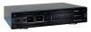
Basic Operation (continued) FRONT PANEL DISPLAY LED DESCRIPTIONS Power On Indicator This LED is illuminated when the utility condition is normal and the UPS outlets are providing clean, protected power. Line Fault Indicator This LED will illuminate to warn the user that a wiring problem such as a bad/missing ground or reversed wiring exists within the AC receptacle. If illuminated, disconnect all equipment and contact an electrician to insure outlet is properly wired. Unsafe Voltage Indicator This LED will illuminate to inform the user that an unsafe line voltage is present and that the UPS has switched to battery power. This could be either an over-voltage or under-voltage. Battery Level Indicator This is a visual indication of the battery charge. If battery capacity is under 25%, no indicator LED will illuminate and UPS starts beeping (if the audible alarm is enabled). Battery Mode Indicator This illuminates during utility failure or an unsafe voltage condition, indicating that the battery is supplying power to the connected equipment. 1 2 3 4 Load Level Indicator This is a visual indication of the UPS load. The 1st arrow will illuminate when the load is above 25%, the 2nd above 50% and the 3rd above 75%. The 4th arrow will flash when the load is between 85% and 100%. AVR Indicator This indicates that the UPS is operating in automatic voltage regulation mode. When the led is illuminated continuously, it indicates an input over-voltage and the UPS unit reduces (bucks) the voltage to the normal operating range. When the led is flashing, it indicates that the input line voltage is low and that the UPS is increasing (boosts) input voltage to the normal range. REAR PANEL DESCRIPTION Non-Critical-Load Outlets Four battery powered, surge protected and AVR outlets for connected equipment insures temporary uninterrupted operation of connected equipment during a power failure. Critical Load Outlets Two battery powered, surge protected and AVR outlets for critical-load equipment insures temporary uninterrupted operation of connected equipment during a power failure. AC Power Cord Input Receptacle IR Control Section Learning Control Switches - Push to program or test the IR function IR Detector Window - Receives the IR signal to be learned Indicator LED's - Indicates learning status Output Delay Switches - Set the desired time delay between a power failure and when the IR signals are sent to the connected equipment IR Output Jacks - Standard 1/8" (3.5mm) mono jack for connection to an IR flasher (IR flashers not included) Circuit Breakers for Overload Protection Resettable circuit breakers provide optimal overload protection. RS232 Serial Communication Port The serial port allows connection and communication between the UPS and a HTPC (home theater personal computer) or home automation system. If used temporarily during setup (with the included software), it allows the installer to program a number of variables including the Critical Load Battery Threshold. See the software documentation for more information. USA & Canada (800) 472-5555 • (707) 283-5900 • Fax (707) 283-5901 RJ11/RJ45 Jacks Ports protect standard telephone line, modem, or network cable. 3
-
 1
1 -
 2
2 -
 3
3 -
 4
4 -
 5
5 -
 6
6 -
 7
7 -
 8
8 -
 9
9 -
 10
10 -
 11
11 -
12
-
13
-
14
-
15
-
16
-
17
-
18
-
19
-
20
 |
 |
